
Get more content that can help you
Content
Modern industrial systems depend on accurate, continuous, and interference-free communication. Automation controllers, distributed control systems, safety monitoring equipment, data acquisition units, industrial computers, and instrumentation networks all require cables that can preserve signal quality while operating in electrically and mechanically challenging environments. In ordinary installations, a conventional control or communication cable may provide adequate performance. However, applications involving strong electromagnetic interference, underground routing, heavy machinery, vibration, moisture, impact, or rodent exposure require a much higher level of protection.
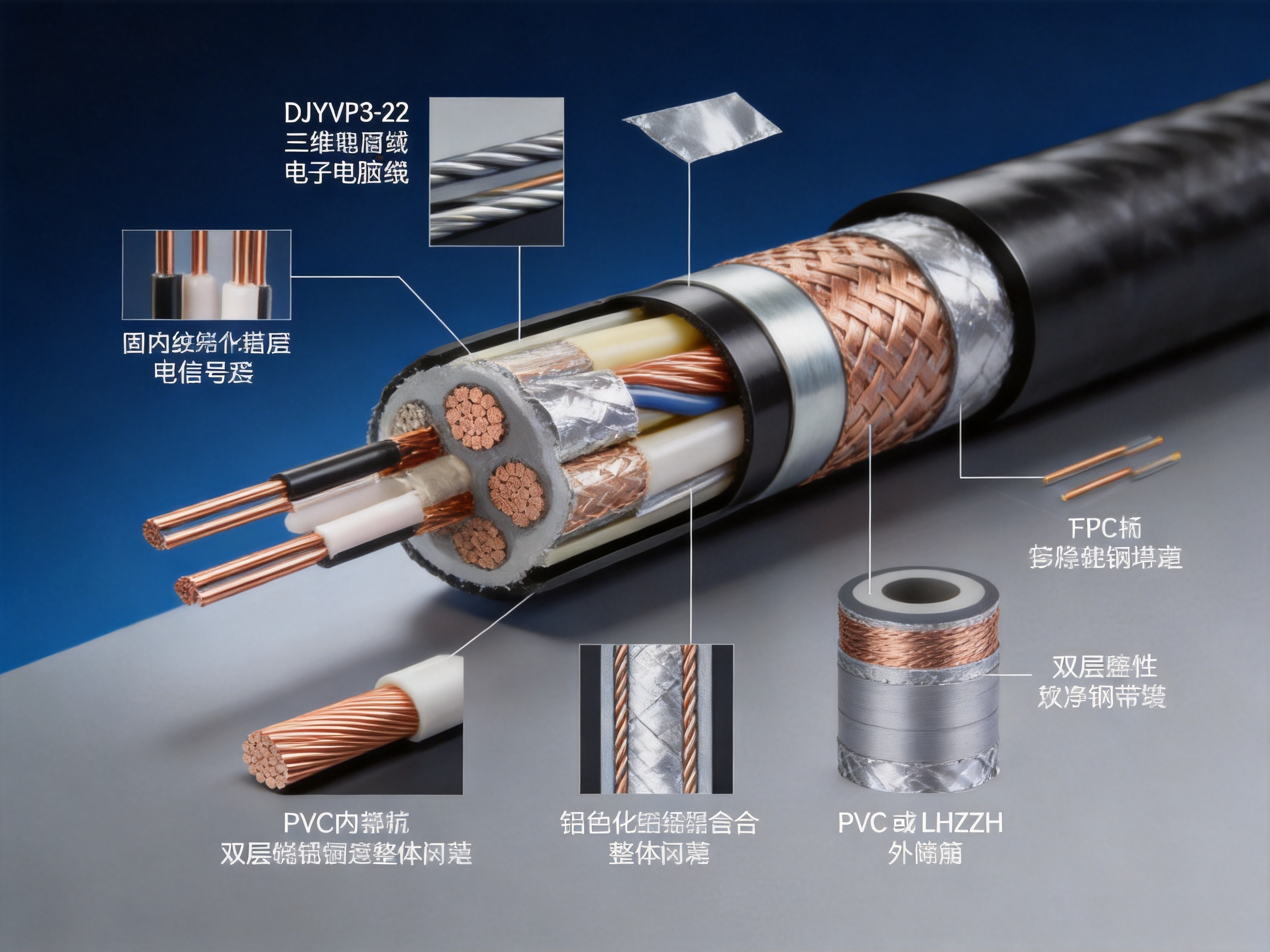
The DJYVP3-22 electronic computer cable is designed for these demanding conditions. It combines twisted-pair signal transmission, triple electromagnetic shielding, double-layer galvanized steel tape armor, moisture-resistant construction, and flexible installation options. This combination makes it suitable for industrial automation, nuclear power facilities, military installations, tunnels, direct-burial projects, pipeline systems, and other signal networks in which transmission accuracy and physical protection are equally important.
Unlike a basic unshielded communication cable, this design is engineered as a complete protection system. The conductors transmit the signal, the twisted-pair arrangement limits crosstalk, the individual pair shields reduce local interference, the overall shields provide additional electromagnetic isolation, and the double-layer armor protects the cable from external mechanical forces. An inner sheath and outer sheath complete the construction, helping protect the internal components against moisture, abrasion, and environmental exposure.
This article examines the cable’s structure, technical characteristics, application value, manufacturing quality, installation compatibility, and advantages compared with less-protected alternatives. It also explains how an experienced cable manufacturer supports customization, production consistency, inspection, and delivery for industrial customers.
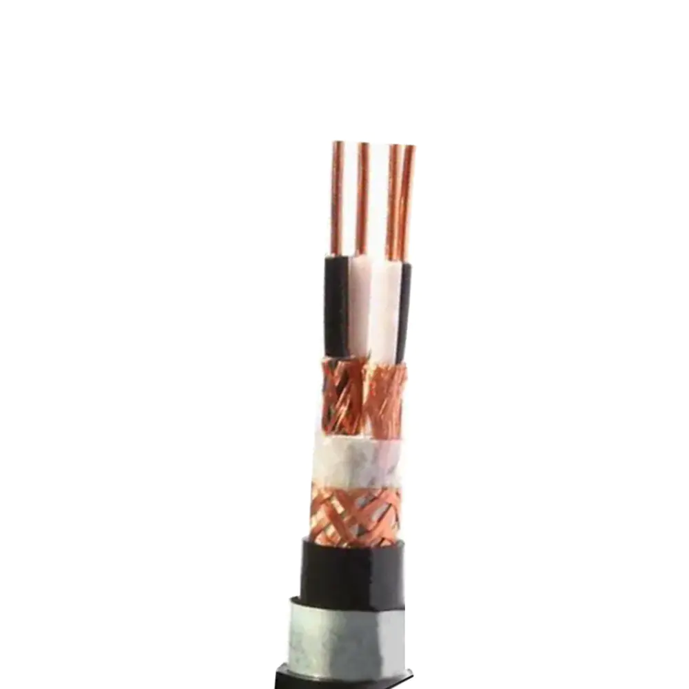
DJYVP3-22 Strong installation compatibility Electronic Computer Cable
Electronic computer cables are used to transfer low-voltage signals between instruments, controllers, sensors, terminals, and monitoring systems. These signals may represent temperature, pressure, flow, speed, position, alarm status, process data, or control instructions. Although the power level is often low, the information carried by the cable can be critical to equipment safety and production stability.
Industrial sites are rarely electrically quiet. Motors, variable-frequency drives, transformers, welding equipment, switching devices, large generators, and high-current conductors can produce electromagnetic fields. When a communication cable is installed near these sources, unwanted energy may be coupled into the signal circuit. The resulting noise can cause inaccurate measurements, communication errors, false alarms, control instability, or intermittent system failures.
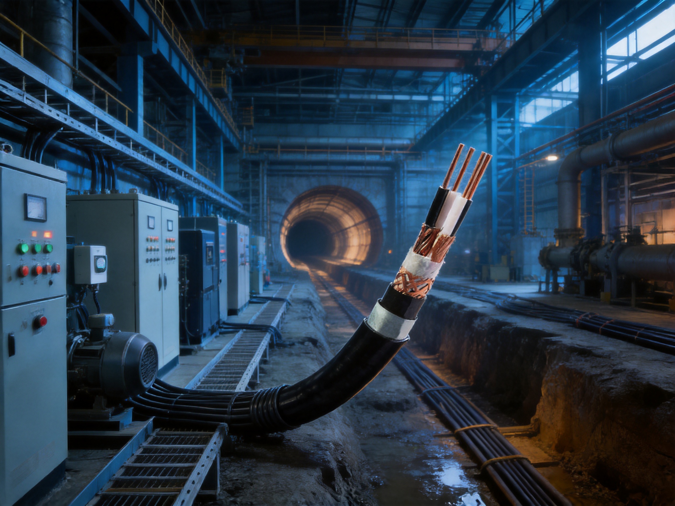
Mechanical conditions can be equally challenging. Cables installed underground may be exposed to soil pressure, stones, construction activity, water, and accidental impact. Cables routed through tunnels or pipelines may encounter pulling forces, abrasion, vibration, and limited access for repair. Outdoor installations may face moisture, temperature variation, ultraviolet exposure, and animals. A cable that only addresses electrical interference but lacks mechanical protection may not provide dependable service in these environments.
The DJYVP3-22 design addresses both categories of risk. Its triple-shielding configuration is intended to reduce electromagnetic interference, while its double-layer steel tape armor provides resistance to compression, impact, and rodent damage. This integrated approach reduces the need to combine separate protective conduits, shielding accessories, and additional mechanical barriers in every installation.
The cable uses solid or stranded annealed copper conductors. Copper is selected for its high electrical conductivity, stable connection performance, and compatibility with common industrial termination methods. Annealing improves flexibility compared with hard-drawn copper, making the conductors easier to process and install.
Solid conductors can offer dimensional consistency and stable electrical characteristics in fixed installations. Stranded conductors can provide improved flexibility where the cable must be routed around equipment, through cabinets, or along a conduit with bends. The availability of both conductor formats allows the design to be matched to the application, installation method, and project specification.
The stated cross-section range is 1.0 mm² to 10.0 mm². This range supports different transmission distances, load requirements, mechanical considerations, and termination preferences. The correct conductor size should be selected according to the signal type, circuit length, voltage drop, operating temperature, installation method, and applicable project standards.
The cable can be manufactured with 1 to 24 twisted pairs. Each pair consists of two insulated conductors twisted together at a controlled lay length. Twisting helps the two conductors experience similar external electromagnetic exposure, allowing induced interference to be reduced when the differential signal is received.
Twisted-pair construction also reduces crosstalk between neighboring circuits. This is especially important when multiple instrument signals share the same cable. A carefully manufactured pair arrangement helps maintain predictable electrical characteristics and supports high-frequency or differential signal transmission within the stated application range.
Pair count flexibility is valuable in industrial projects. A small monitoring circuit may require only one or two pairs, while a large automation system may need many pairs for sensors, status signals, communication channels, and spare circuits. A single cable family that supports different pair counts can simplify system design, procurement, and maintenance planning.
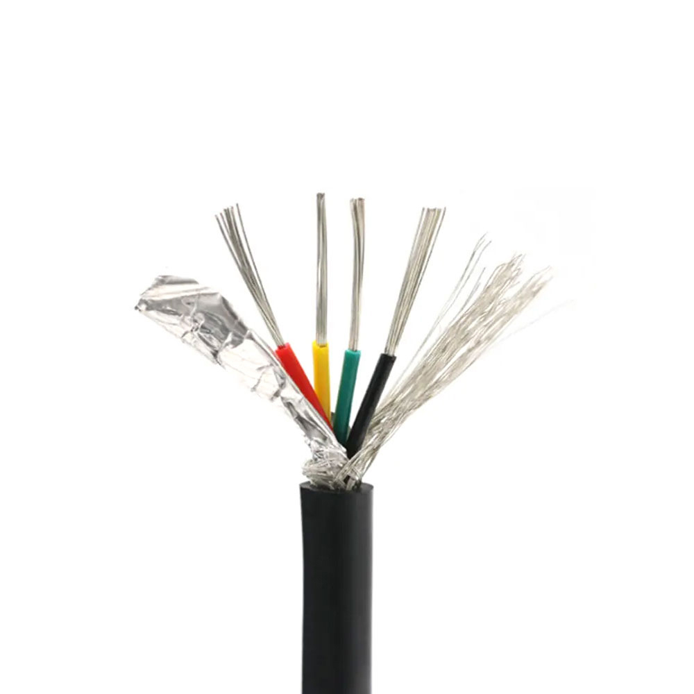
The distinguishing feature of the DJYVP3-22 is its triple-shielded structure. The construction includes aluminum foil shielding with a tinned copper drain wire for each pair, a copper braid shield, and an aluminum-polyester composite tape overall shield. These layers provide multiple paths for controlling unwanted electromagnetic energy.
Individual pair shielding helps isolate one signal circuit from another and reduces the influence of localized interference. The tinned copper drain wire provides a practical grounding and bonding path for the foil layer when the cable is terminated correctly. The copper braid contributes a conductive shielding layer with mechanical flexibility and broad coverage.
The overall aluminum-polyester composite tape adds another barrier around the cable assembly. Depending on grounding practice, installation design, and frequency characteristics, the combined shielding layers can improve electromagnetic compatibility compared with a cable that relies on only one foil or braid layer.
Shielding performance depends not only on the cable itself but also on installation quality. The shield should be terminated in accordance with the system grounding design. Poorly prepared shield connections, excessive pigtail length, incorrect bonding, or inconsistent grounding can reduce the benefits of even a highly protected cable. For this reason, cable selection and installation engineering should be considered together.
After the insulated, shielded, and filled core is assembled, the cable receives double-layer galvanized steel tape wrapped armor. This armor increases resistance to external compression, impact, crushing forces, and rodent attack.
The double-layer arrangement offers a higher level of mechanical protection than a single layer of tape. It is particularly useful where the cable may be exposed to direct burial, underground construction, industrial traffic, vibration, or contact with rough surfaces. The galvanized finish helps improve resistance to corrosion under appropriate environmental conditions, although the complete cable selection must still account for soil chemistry, water exposure, and installation practices.
Armor also improves installation flexibility. Depending on local codes and project requirements, an armored cable may be routed directly underground or installed in conduit. This can reduce the number of separate protective components needed and may simplify the design of long cable routes.
The internal assembly is protected by a PVC inner sheath with a stated thickness range of 1.2 mm to 1.8 mm. The inner sheath helps bind and protect the shielded core before the armor is applied. It also creates separation between internal electrical components and the armor structure.
The outer sheath is available in PVC or low-smoke zero-halogen material. The stated outer sheath thickness range is 2.5 mm to 3.5 mm. PVC provides a widely used balance of mechanical durability, processability, and cost effectiveness. LSZH material can be selected where smoke emission and halogen-free performance are important, such as enclosed public facilities, transportation areas, control rooms, and projects with strict fire-safety requirements.
Sheath selection should be based on the complete environmental profile. Factors may include fire requirements, smoke restrictions, oil or chemical exposure, temperature, sunlight, moisture, installation location, and applicable standards. Offering both PVC and LSZH alternatives gives project engineers greater flexibility during specification.
The following table summarizes the principal characteristics provided for the DJYVP3-22 cable. Actual production values may vary according to conductor size, pair count, sheath selection, customized construction, and the applicable technical agreement.
Item | Specification | Engineering Significance |
Conductor | Solid or stranded annealed copper | Good conductivity and installation adaptability |
Cross-section | 1.0 mm² to 10.0 mm² | Supports different circuit and distance requirements |
Number of pairs | 1 pair to 24 pairs | Suitable for small and complex signal networks |
Rated voltage | 300/500 V | Designed for low-voltage control and signal applications |
Test voltage | 3 kV AC for 1 minute | Supports insulation integrity verification |
Insulation | Polyethylene | Provides stable insulation and high resistance |
Shielding | Pair foil and drain wire, copper braid, overall composite tape | Three-stage electromagnetic protection |
Armor | Double-layer galvanized steel tape | Improves resistance to impact, compression, and rodents |
Inner sheath | PVC, 1.2 mm to 1.8 mm | Protects the assembled core before armoring |
Outer sheath | PVC or LSZH, 2.5 mm to 3.5 mm | Provides environmental and fire-related options |
Characteristic impedance | 100 Ω ±6 Ω | Supports controlled signal transmission |
Capacitance unbalance | Not greater than 50 pF/100 m at 1 kHz | Helps maintain pair balance |
Working capacitance | Not greater than 52 nF/km | Supports predictable circuit behavior |
Attenuation | Not greater than 1.0 dB/100 m at 1 MHz | Limits signal loss within the specified condition |
Insulation resistance | At least 10,000 MΩ·km | Indicates strong insulation performance |
A basic unshielded twisted-pair cable may be suitable for a clean electrical environment, but its performance can be compromised when installed beside high-current power cables, variable-frequency drives, motors, or switching equipment. A single-shielded design may provide an improvement, yet it may not be sufficient in facilities with strong and variable electromagnetic fields.
The DJYVP3-22 uses shielding at the pair level and across the complete cable assembly. This layered arrangement gives it a practical advantage where signal integrity is a primary concern. It can reduce the likelihood that external noise will enter the signal circuit and can also limit interaction between adjacent pairs.
Its value is particularly clear in applications where the cost of a communication error is high. A false sensor reading, missed alarm, or unstable control command can cause downtime, product loss, equipment damage, or safety concerns. A higher-protection cable may therefore provide lower total project risk even if its initial purchase price is greater than that of a basic cable.
Unarmored cables usually require conduit, cable tray covers, protective tubing, or other external barriers when exposed to impact or crushing. These additional systems can increase installation time and material cost. They may also create more connection points and access requirements.
The double-layer steel tape armor integrated into the DJYVP3-22 provides built-in protection. It is suitable for cable routes where the cable may be buried, placed in a tunnel, routed near industrial equipment, or exposed to rodents. The armored structure also gives installers greater confidence during handling and routing, although recommended bend radius and pulling procedures must still be followed.
Some communication cables are intended only for protected indoor routes. Others may require a dedicated conduit throughout their entire length. The DJYVP3-22 is designed for more varied installation conditions, including direct burial or conduit installation where permitted by project requirements.
This flexibility can be valuable in large industrial facilities. Cable routes may pass through control rooms, equipment areas, trenches, tunnels, outdoor sections, and underground passages. Using a cable with integrated shielding and armor can reduce transitions between different cable types and simplify procurement.
Critical systems require a higher margin of protection. Nuclear power plants, military facilities, high-interference production lines, and safety monitoring installations cannot always rely on the minimum cable construction. The DJYVP3-22 has been specified for environments where electromagnetic compatibility and mechanical durability are both important.
The cable does not eliminate the need for correct system design, grounding, routing, testing, and maintenance. However, it provides a stronger foundation for a reliable signal network than a basic unshielded or lightly protected alternative.
The availability of an LSZH outer sheath is another advantage for projects with strict smoke and halogen requirements. In a fire, low-smoke materials can help reduce dense smoke generation, while zero-halogen materials are selected to limit halogen-containing emissions. This can be important in enclosed spaces and areas where evacuation, equipment protection, or sensitive electronics are priorities.
LSZH should be selected only after confirming the required mechanical, chemical, thermal, and fire-performance specifications. In some outdoor or industrial applications, a particular PVC formulation may offer a more suitable balance of durability and cost. The ability to select between sheath materials allows the cable configuration to be tailored rather than treated as a one-size-fits-all product.
Power-generation facilities contain extensive instrumentation and control networks. These networks monitor operating conditions, transmit alarms, and support automation functions. The presence of large generators, transformers, motors, switching systems, and high-current conductors creates a demanding electromagnetic environment.
In such facilities, cable selection should prioritize signal stability, mechanical protection, fire performance, and traceability. The DJYVP3-22 can be considered for suitable low-voltage instrumentation and computer signal circuits where its rated voltage, temperature, fire, radiation, and environmental requirements are compatible with the project specification.
For nuclear projects in particular, the cable must be evaluated against the complete set of plant-specific requirements. The product’s triple shielding and armored construction offer useful design features, but final approval should be based on formal qualification, environmental testing, and documentation required by the plant owner or regulatory authority.
Military facilities and security systems may require controlled signal transmission in areas containing communication equipment, radar-related systems, power conversion devices, and other sources of electromagnetic activity. Physical access may also be limited, making long-term cable dependability important.
The combination of pair shielding, overall shielding, and steel tape armor provides a practical solution for protected signal routes. The cable can support monitoring, control, communications infrastructure, and equipment interconnection when matched with the required electrical and environmental specifications.
Industrial automation systems rely on sensors, programmable controllers, remote input and output units, industrial computers, actuators, and supervisory software. These components must communicate accurately despite the operation of motors, drives, robots, conveyors, welding equipment, and other machinery.
The twisted-pair structure helps reduce crosstalk, while the triple shielding supports electromagnetic compatibility. The cable can be used in control cabinets, production lines, equipment rooms, cable trenches, and other areas where signal integrity affects manufacturing efficiency.
Tunnels and underground routes often combine restricted access, moisture, mechanical exposure, and challenging installation conditions. Maintenance can be expensive when a cable fails because replacement may require traffic control, excavation, or specialized access equipment.
The armored construction helps protect against external forces, while the sheath system provides a barrier against moisture and wear. Where fire safety is a major concern, an LSZH outer sheath may be considered subject to the project’s complete requirements.
Pipeline stations, pump systems, chemical plants, and process facilities use signals from pressure, temperature, flow, and safety instruments. The cable may be routed outdoors, underground, in trenches, or through equipment areas with significant electromagnetic activity.
Before installation, engineers should evaluate chemical exposure, oil resistance, temperature, moisture, ultraviolet exposure, grounding, and separation from power circuits. The DJYVP3-22 provides a strong structural platform, while the final sheath and accessory selection should be adapted to the actual environment.
Direct burial can reduce the need for continuous conduit, but it places greater responsibility on cable construction and installation quality. The route must be prepared properly, sharp objects must be removed, the minimum burial depth must be observed, and the cable must not be subjected to excessive pulling or bending stress.
Double-layer steel tape armor gives the cable an advantage in direct-burial applications because it provides integrated mechanical protection. Drainage, water ingress prevention, joint sealing, and grounding must still be addressed as part of the overall cable system.
Anhui Zhishang Cable Technology Co., Ltd. integrates research and development, production, and sales. This structure allows technical requirements to be communicated more directly between customers, engineers, production personnel, and quality teams. It also supports faster feedback when a cable must be adjusted for pair count, conductor construction, sheath material, armor design, or project-specific requirements.
The company’s stated business philosophy emphasizes quality orientation, integrity, and stability. For industrial cable buyers, these principles are important because a cable is not merely a commodity length of copper and polymer. It is a long-term component of an electrical system, and its consistency affects installation, commissioning, maintenance, and operational reliability.
The company operates a production base of approximately 5,000 square meters with 10 automated production lines. Automation can improve repeatability in conductor processing, insulation extrusion, twisting, shielding, sheathing, and cable take-up. It can also reduce variation caused by manual handling when production parameters are properly controlled.
Automated equipment does not replace technical expertise. Instead, it provides a stable manufacturing platform that must be supported by process instructions, calibration, material controls, inspection procedures, and trained personnel. The combination of automated production and experienced engineers helps support consistent cable dimensions and electrical performance.
The stated monthly output capacity reaches up to 10 million meters. This capacity can support both standard product orders and larger project requirements. Capacity is particularly relevant when a project requires multiple pair counts, conductor sizes, or sheath configurations within a coordinated delivery schedule.
Standard products may be stocked for faster shipment, while customized products typically require a lead time of 7 to 20 days. Actual timing depends on the construction, quantity, raw material availability, testing requirements, packaging, and customer approval process. Early technical confirmation helps reduce delays, especially for armored and multi-shielded products that require several sequential production stages.
The company describes quality assurance based on full-core, full-length, and pure-copper specifications for standard cable models. This approach is important because cable quality cannot be judged only by a short sample. Defects such as conductor discontinuity, insulation damage, uneven shielding, sheath irregularity, or inconsistent armor application may occur at isolated points along a long production length.
Continuous production monitoring and appropriate electrical testing can help identify these issues before shipment. For project applications, buyers should request the relevant inspection records, test reports, dimensional information, material declarations, and product identification details required by their quality system.
The company employs more than 50 people, including quality engineers and research and development technicians with more than 10 years of industry experience. Experienced personnel are valuable when translating a project requirement into a practical cable construction.
For example, a customer may provide a drawing that specifies a conductor size but does not define the shield termination, filler arrangement, armor coverage, sheath material, or bending requirements. Technical engineers can review the complete application and identify details that influence manufacturing feasibility and field performance.
Custom cable projects often require more than selecting a catalog item. Customers may need a special pair count, different insulation thickness, modified color coding, specific printing, alternative sheath material, special packing length, or a construction based on an existing sample.
The company supports OEM and ODM development based on customer drawings or samples. This capability allows the product to be adapted to a system architecture rather than forcing the system to use a standard cable that may not fully satisfy its requirements. Customization should be confirmed through a written technical specification, sample approval, and defined inspection criteria.
Manufacturing begins with the selection and preparation of annealed copper conductors. The conductor is drawn or processed to the required cross-section, then inspected for diameter, surface condition, resistance, and continuity. If stranded conductors are specified, individual wires are assembled with controlled lay and tension.
Stable conductor geometry is essential because variations affect insulation thickness, overall diameter, flexibility, resistance, and termination performance. Material identification and batch control also help maintain traceability through later production stages.
Polyethylene insulation is extruded around each conductor. The stated insulation thickness range is 0.5 mm to 1.2 mm, depending on the cable configuration and electrical requirements. Extrusion control must maintain a uniform wall thickness and a smooth surface without voids, inclusions, or damage.
After extrusion, the insulated conductors are cooled, measured, and tested. Typical checks may include dimensional inspection, spark testing, insulation resistance, color identification, and conductor continuity. Proper insulation quality is fundamental to the cable’s rated voltage and long-term electrical stability.
Insulated conductors are twisted into pairs using controlled production parameters. Lay length influences electrical balance, crosstalk, flexibility, and capacitance. Pair identification is maintained through color coding, numbering, or other agreed methods.
When a cable contains many pairs, accurate identification becomes a major installation advantage. Clear pair marking reduces termination errors, shortens commissioning time, and simplifies future troubleshooting. The manufacturing process should preserve pair geometry and prevent unnecessary untwisting during shielding and core assembly.
Each pair receives aluminum foil shielding and a tinned copper drain wire. The foil must be applied with suitable overlap and consistent coverage. The drain wire must remain electrically accessible and positioned correctly for termination.
Pair-level shielding is especially valuable when multiple sensitive circuits are contained in the same cable. It helps reduce pair-to-pair interaction and limits the effect of local electromagnetic fields. Production checks should verify shield continuity, coverage, drain-wire placement, and resistance where applicable.
The required number of pairs is assembled into a cable core. Non-hygroscopic polypropylene yarn is used as filling material to help maintain a round, stable core and reduce voids between the pairs. The non-hygroscopic property helps limit moisture retention within the cable structure.
Core assembly requires controlled tension. Excessive tension can deform the pairs or affect capacitance, while insufficient control can create loose areas and irregular diameter. A consistent core supports uniform application of the inner sheath and armor.
The assembled core receives a copper braid shield and an aluminum-polyester composite tape overall shield. These layers complete the triple-shielding arrangement. The braid provides a flexible conductive layer, while the composite tape offers additional coverage around the full cable core.
Shield overlap, braid coverage, continuity, and bonding design are important quality factors. The overall shield must be applied without damaging the inner sheath or creating excessive stiffness. The process should also maintain a stable cable diameter for subsequent armoring and outer sheathing.
The shielded core is covered with a PVC inner sheath. This sheath stabilizes the assembly and provides separation before the armor is applied. Its thickness is controlled within the specified range according to the cable design.
During extrusion, technicians monitor temperature, pressure, line speed, diameter, surface finish, and adhesion. A smooth and uniform inner sheath improves the armor application process and helps protect the shield system from mechanical contact.
Galvanized steel tape is wrapped around the inner-sheathed core in two layers. The wrapping tension, overlap, alignment, and surface condition must be controlled carefully. Proper armor application protects the cable without creating excessive deformation or restricting the required flexibility.
Armor continuity and coverage are important for both mechanical and grounding considerations. The finished cable should be evaluated for outer diameter, surface condition, bending behavior, and resistance to handling stresses appropriate to the design.
The final PVC or LSZH outer sheath is extruded over the armored cable. The outer sheath protects the armor and provides the cable’s primary environmental interface. Printing may identify the product type, conductor or pair configuration, voltage rating, manufacturer information, production marking, and length.
Final inspection may include appearance, dimensions, conductor resistance, insulation resistance, withstand voltage, shielding continuity, capacitance, impedance, attenuation, and other customer-specified tests. Cable lengths are measured, packaged, labeled, and prepared for shipment according to the order requirements.
Before ordering, engineers should confirm the number of pairs, conductor cross-section, solid or stranded construction, rated voltage, insulation material, shield arrangement, armor requirements, sheath material, and required cable length. The 300/500 V rating should not be interpreted as permission to use the cable outside the limits of the complete system design.
Signal type, transmission distance, termination equipment, grounding method, operating temperature, and relevant standards should also be reviewed. If the cable will carry a specialized communication protocol, the system designer should confirm that the stated impedance, capacitance, attenuation, and pair configuration are compatible with the equipment.
Even a triple-shielded cable should be routed thoughtfully. Where possible, signal cables should be separated from high-voltage and high-current power cables. Parallel runs beside variable-frequency drive outputs, motor conductors, welding circuits, or switching equipment should be minimized or properly separated.
Crossing power cables at approximately right angles can reduce the length of parallel exposure. Cable trays should not be overloaded, and the route should avoid sharp edges, excessive heat, standing water, chemical contamination, and locations where the cable may be repeatedly struck or dragged.
Armored cable is mechanically robust, but it is not indestructible. The minimum bending radius should be obtained from the approved product data or technical agreement. Tight bends can deform the armor, compress the shield, or stress the insulation and sheath.
During pulling, the force should be controlled and distributed appropriately. Pulling directly on an unprepared sheath or shield may cause damage. Rollers, guides, suitable pulling devices, and correct drum handling should be used on long routes. Cable drums should be stored upright and protected from water, impact, and contamination.
The performance of a shielded cable depends strongly on termination. Pair drain wires, braid shields, and overall foil shields should be connected according to the grounding strategy established by the system designer. Shield bonding may differ between instrumentation, communication, control, and safety systems.
Excessive pigtails can increase inductive impedance at higher frequencies. Shield connections should be short, secure, and protected against corrosion. The armor bonding method should also be defined, especially where the cable enters metal cabinets, junction boxes, trays, or equipment enclosures.
During installation, cable ends should be sealed against moisture and contamination. Unprotected ends can allow water to enter the cable structure, particularly when the cable is stored outdoors or installed in wet conditions. Joints and terminations should use accessories compatible with the cable diameter, armor, shield system, sheath material, and environmental exposure.
For direct-burial installations, underground joints should be designed for the expected water, soil, temperature, and mechanical conditions. Any joint that cannot maintain the cable’s protection level may become the weakest point in the system.
Reliable cable procurement requires more than a product description. Buyers should define the inspection and documentation package before production begins. The requirements may include conductor material confirmation, dimensional records, resistance values, insulation resistance, withstand voltage, shield continuity, armor construction, sheath material, packaging details, and marking information.
The stated test voltage for this cable is 3 kV AC for one minute. This test is used to verify insulation integrity under the defined test conditions. It should be performed using suitable equipment and procedures, with the test voltage and duration confirmed against the approved technical specification.
The stated insulation resistance is at least 10,000 MΩ·km. High insulation resistance supports separation between conductors and the surrounding structure. It is particularly important where moisture, long cable lengths, and sensitive measurement circuits are involved.
Capacitance unbalance is stated as no greater than 50 pF/100 m at 1 kHz, while working capacitance is stated as no greater than 52 nF/km. These values help engineers evaluate signal balance, loading, and transmission behavior. Characteristic impedance is specified as 100 Ω ±6 Ω, and attenuation is specified as no greater than 1.0 dB/100 m at 1 MHz.
Testing should be interpreted in relation to the cable configuration. Conductor size, pair count, lay length, shield arrangement, temperature, and measurement method can influence results. A professional manufacturer should provide test conditions and clarify whether values are typical, guaranteed, or subject to a particular standard.
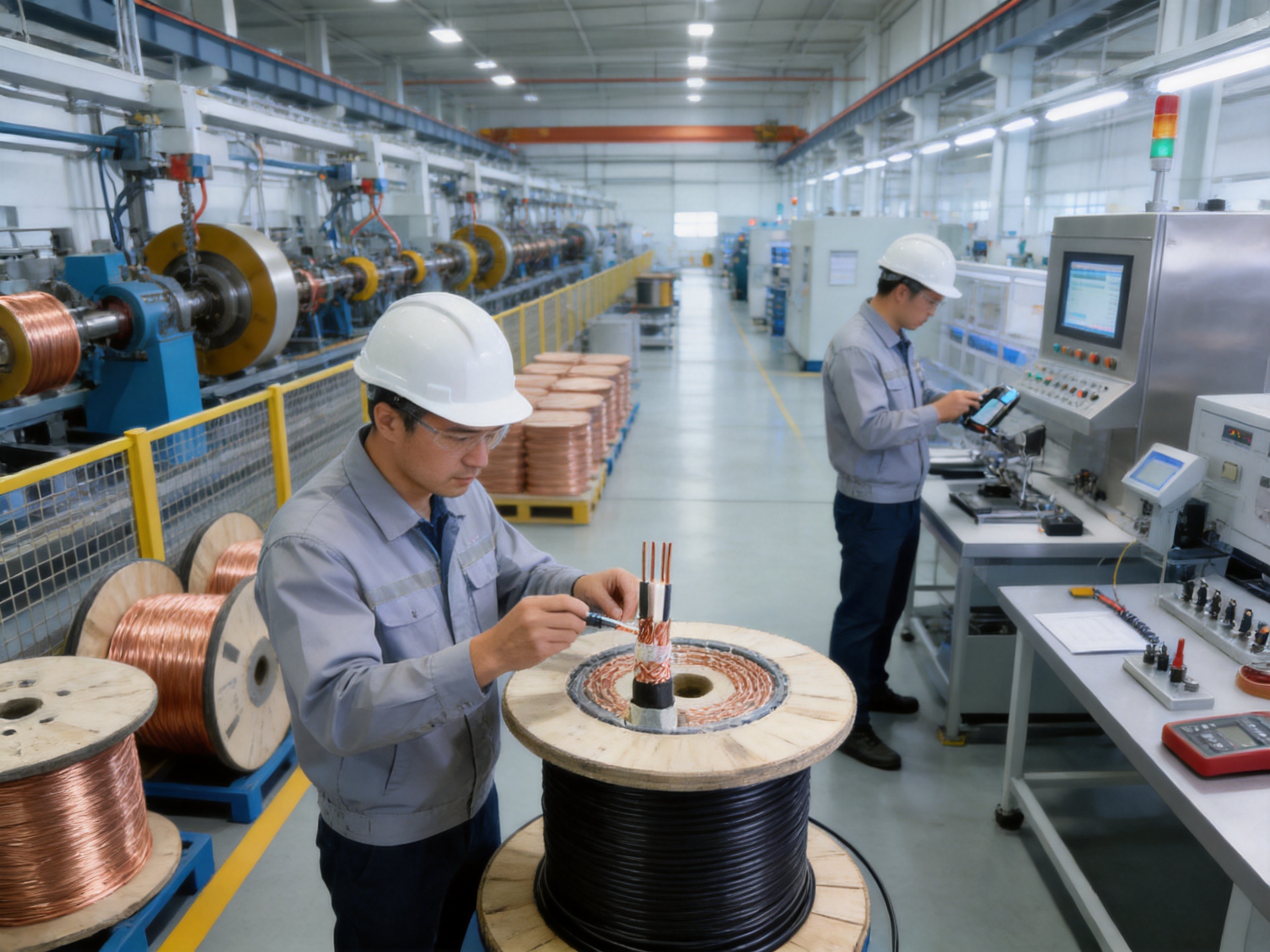
The first selection step is to identify how many independent signal circuits are required. The product supports 1 to 24 pairs. Engineers should consider current circuits, future expansion, maintenance spares, alarm channels, and redundant paths.
Choosing a cable with spare pairs may increase initial cost slightly but can reduce the need for future cable replacement. However, excessive pair capacity can increase diameter, weight, bending requirements, and termination complexity. The best selection balances present needs with realistic expansion plans.
The 1.0 mm² to 10.0 mm² range allows the cable to be adapted to different applications. Smaller conductors may be adequate for low-current instrumentation and short signal paths. Larger conductors may be preferred for longer routes, circuits with higher current, increased mechanical robustness, or specific terminal requirements.
Conductor size should be selected based on actual electrical calculations rather than simply choosing the largest available option. Larger conductors can increase cable diameter and reduce flexibility, while undersized conductors may produce excessive voltage drop or fail to meet the circuit requirement.
PVC is widely used for general industrial applications and can provide good mechanical and environmental performance when the formulation is properly selected. LSZH is appropriate where smoke and halogen restrictions are specified. The choice should be made in coordination with the fire strategy, installation location, local code, and customer requirements.
Solid conductors are often suitable for fixed, carefully supported wiring. Stranded conductors are generally more convenient where routing requires flexibility or where the cable is connected to equipment that may experience movement. The correct choice depends on installation geometry, terminal design, vibration, and maintenance practice.
Purchasing teams sometimes compare cables only by price per meter. This approach can overlook the cost of conduit, installation labor, grounding accessories, shielding components, maintenance access, replacement downtime, and system faults. A highly protected cable may have a higher unit price but a lower total cost of ownership in demanding environments.
The integrated armor can reduce the need for additional mechanical protection. The triple shielding can reduce the risk of communication problems caused by electromagnetic interference. The flexible pair-count and conductor options can reduce the need for multiple cable types. The availability of standard stock and customized production can improve project scheduling.
Reliability value is especially important when cable replacement is difficult. In a tunnel, underground facility, production line, or critical power station, a cable failure may require shutdowns, excavation, restricted access, or specialized labor. Selecting a suitable cable at the design stage can help avoid these indirect costs.
Responsible cable production includes material efficiency, process control, waste reduction, product durability, and appropriate material selection. A cable that remains functional for a long service period can reduce the environmental and economic impact associated with premature replacement.
The company emphasizes green manufacturing and responsible production practices. The availability of LSZH sheath options also supports projects that have specific environmental and fire-safety objectives. Customers should review material declarations and project requirements to verify the suitability of insulation, sheath, filler, shielding, and armor materials for the intended application.
Pure copper conductors, stable production processes, and quality inspection contribute to predictable performance. Accurate cable length and controlled packaging can also reduce installation waste. For custom projects, close coordination between the customer and manufacturer helps prevent unnecessary production of unsuitable or incorrectly configured cable.
A successful custom cable project begins with a complete technical inquiry. The customer should provide the intended application, pair count, conductor size, conductor type, voltage, insulation material, shielding requirements, armor requirements, sheath material, environmental conditions, cable length, packaging requirements, and applicable standards.
Drawings, samples, photographs, equipment manuals, and installation descriptions can help the engineering team understand the project. If the cable will be installed in a high-interference zone, the customer should describe the nearby equipment and grounding arrangement. If it will be buried or exposed outdoors, soil, water, temperature, chemical, and mechanical conditions should be identified.
The manufacturer can then recommend a suitable construction and clarify which parameters are standard, optional, or subject to engineering confirmation. Prototype or sample approval may be appropriate for special configurations. Before mass production, both parties should confirm the final specification, inspection plan, labeling, delivery schedule, and acceptance criteria.
With a production base of approximately 5,000 square meters, 10 automated production lines, and a stated monthly capacity of up to 10 million meters, the company can support standard products as well as project-based requirements. Its technical team provides OEM and ODM development based on drawings or samples, which is valuable when an existing standard cable does not meet the complete system requirement.
The DJYVP3-22 is differentiated by the combination of multiple protective features rather than by a single material or component. Its copper conductors provide the electrical path. Its twisted pairs reduce crosstalk and support balanced signal transmission. Individual pair shielding limits local interference. The copper braid and overall composite tape add further electromagnetic protection. The PVC inner sheath stabilizes the assembly, while the double-layer galvanized steel tape armor provides mechanical protection. The PVC or LSZH outer sheath allows environmental and fire-related customization.
Compared with ordinary unshielded computer cable, it offers a higher level of electromagnetic and mechanical protection. Compared with a cable using only one shield, its triple-shielded design provides an additional defense against interference. Compared with an unarmored cable, its steel tape armor is better suited to direct burial, tunnels, industrial sites, and areas exposed to impact or rodents.
Its advantages are most meaningful when matched with proper installation. Cable routing, grounding, shield termination, bending control, moisture sealing, and testing all influence final performance. The product should therefore be specified as part of a complete signal transmission system rather than treated as an isolated component.
The cable is designed for electronic computer, instrumentation, control, and signal transmission systems that require strong electromagnetic interference resistance and mechanical protection. It is intended for demanding industrial and infrastructure environments.
The construction includes aluminum foil shielding with a tinned copper drain wire for each pair, a copper braid shield, and an aluminum-polyester composite tape overall shield. These three shielding elements work together to improve electromagnetic compatibility when properly installed and grounded.
The double-layer galvanized steel tape armor improves resistance to compression, impact, abrasion-related mechanical stress, and rodent damage. It supports applications such as direct burial, tunnel routing, industrial installation, and complex underground cable paths.
The stated range is 1 pair to 24 pairs. The correct pair count should be selected according to the required signal circuits, spare capacity, cable diameter, installation space, and termination plan.
Its armored structure facilitates direct-burial installation where permitted by the project specification and local requirements. Proper burial depth, route preparation, drainage, end sealing, joint protection, grounding, and mechanical handling remain essential.
Yes. The armored construction is compatible with conduit installation when the conduit diameter, bend radius, pulling force, heat dissipation, and installation method are suitable. The cable should not be forced through undersized or sharply bent conduit.
The outer sheath can be PVC or LSZH. PVC is suitable for many general industrial applications, while LSZH may be selected for projects requiring reduced smoke and zero-halogen characteristics. The final choice should be based on the complete environmental and fire-safety specification.
The stated rated voltage is 300/500 V. Engineers should confirm that the circuit voltage, installation environment, and applicable standards are compatible with this rating.
The cable uses solid or stranded annealed copper conductors. The available cross-section range is 1.0 mm² to 10.0 mm².
Twisting helps the two conductors in a pair experience similar external interference and reduces crosstalk between neighboring circuits. It also supports balanced and differential signal transmission.
Yes. Its triple-shielded structure is specifically intended to improve electromagnetic compatibility in high-interference industrial zones, power facilities, military environments, and automation systems. Correct routing, grounding, and shield termination are still required.
Yes. The manufacturer supports OEM and ODM development based on customer drawings or samples. Customization may involve pair count, conductor construction, insulation, shield arrangement, sheath material, printing, packaging, or other agreed parameters.
Customized products typically require 7 to 20 days according to the stated company information. Actual lead time depends on quantity, material availability, construction complexity, testing requirements, and customer approval.
Depending on the project, buyers may request product specifications, material information, routine test reports, conductor resistance results, insulation resistance results, withstand-voltage records, dimensional data, shield and armor details, packaging records, and conformity documentation required by the purchasing organization.
No cable should be assumed to meet a specialized nuclear, military, fire, radiation, or security qualification without formal evidence. The DJYVP3-22 provides suitable design features for demanding applications, but project-specific qualification, testing, documentation, and approval must be confirmed separately.
The DJYVP3-22 electronic computer cable is a high-protection solution for signal transmission systems that operate in electrically noisy and mechanically demanding environments. Its combination of twisted-pair construction, triple electromagnetic shielding, double-layer galvanized steel tape armor, polyethylene insulation, protective sheaths, and flexible configuration options provides a strong foundation for reliable industrial communication.
Its advantages over less-protected cables include improved resistance to electromagnetic interference, greater mechanical protection, direct-burial and conduit installation compatibility, better suitability for critical infrastructure, and the option of an LSZH outer sheath. These features make it suitable for industrial automation, power facilities, military installations, tunnels, pipelines, underground networks, and other applications where signal accuracy and cable durability are essential.
The product’s value is further supported by the manufacturer’s integrated research, production, and sales structure, modern production facilities, automated production lines, experienced engineering and quality personnel, OEM and ODM capabilities, standard product inventory, and project-oriented delivery support. With proper specification, manufacturing control, installation, grounding, and testing, the cable can help form a dependable signal infrastructure for demanding industrial systems.
1. Product technical information for DJYVP3-22 triple-shielded armored electronic computer cable, including construction, electrical characteristics, shielding, armor, and application data.
2. General engineering practices for industrial instrumentation and electronic computer cable selection, routing, shielding, grounding, and termination.
3. Technical guidance for twisted-pair transmission systems, electromagnetic compatibility, capacitance balance, characteristic impedance, and signal attenuation.
4. General cable manufacturing principles covering copper conductor preparation, polymer insulation extrusion, pair twisting, shielding, filling, armoring, sheathing, and final inspection.
5. Fire-safety considerations for PVC and low-smoke zero-halogen cable sheath materials in industrial, infrastructure, and enclosed installations.
6. Industrial cable installation practices for direct burial, conduit routing, underground cable protection, cable pulling, bending control, joint sealing, and grounding.

We firmly believe that good cables are not only a competition of materials, but also a reflection of craftsmanship, quality, and responsibility.

Links
Product
Send Inquiry
No. 29 Sankeshu Road, Xuanzhou District, Xuancheng City, Anhui Province, China
+86-18621104555/+86-563-2622999
 Electrical Cable Manufacturer
OEM/ODM Wire and Cable Solutions
 English
 Español
 عربى
 русский