

Get more content that can help you
Content
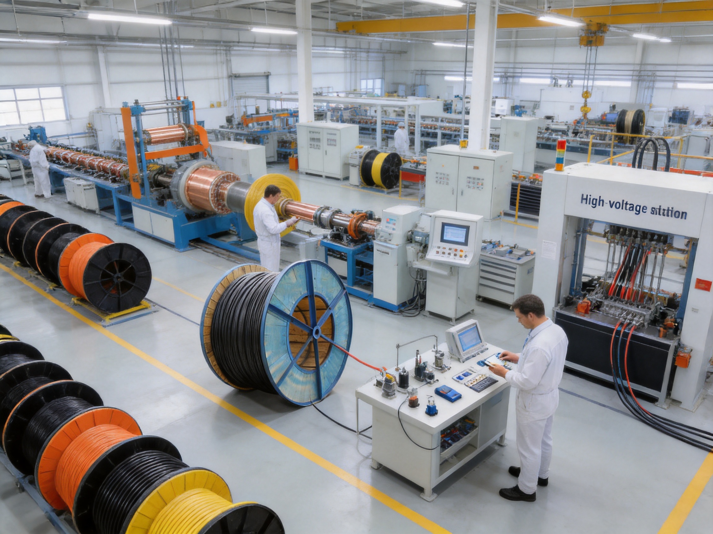
High-voltage cable systems used in mobile equipment, lifting machinery, mining installations, port facilities, generator sets, and temporary power networks must perform reliably under conditions that are considerably more severe than those found in ordinary fixed wiring. These cables may be bent repeatedly, exposed to oil and rain, subjected to abrasion, installed in areas with electromagnetic interference, or required to transmit power while equipment is moving continuously. A cable that performs well in a clean indoor environment may fail prematurely when exposed to vibration, torsion, mechanical impact, temperature changes, or chemical contamination.
The JF and JBF series high-voltage flexible cables are designed for these demanding conditions. Their construction combines stranded or compacted copper conductors, cross-linked polyethylene or ethylene propylene rubber insulation, copper wire braid shielding, and a chloroprene rubber or chlorinated polyethylene sheath. This combination provides a balance of electrical performance, mechanical flexibility, environmental durability, and shielding effectiveness.
Unlike conventional rigid power cables, these flexible cables are intended to support equipment that moves, bends, lifts, rotates, or changes position. They are available across a wide cross-section range from 2.5 mm² to 300 mm² and can be produced for rated voltages including 450/750 V, 0.6/1 kV, 1.8/3 kV, and 3.6/6 kV. This broad specification range allows the same product family to serve control-power interfaces, mobile machinery, industrial power distribution, and specialized high-voltage equipment.
The product is manufactured by Anhui Zhishang Cable Technology Co., Ltd., a Chinese cable manufacturer integrating research and development, production, testing, and sales. Its production capability includes more than 5,000 square meters of modern facilities, 10 automated production lines, and a reported monthly output of up to 10 million meters. These resources support both standard cable production and customized OEM/ODM development based on technical drawings, samples, or defined project requirements.
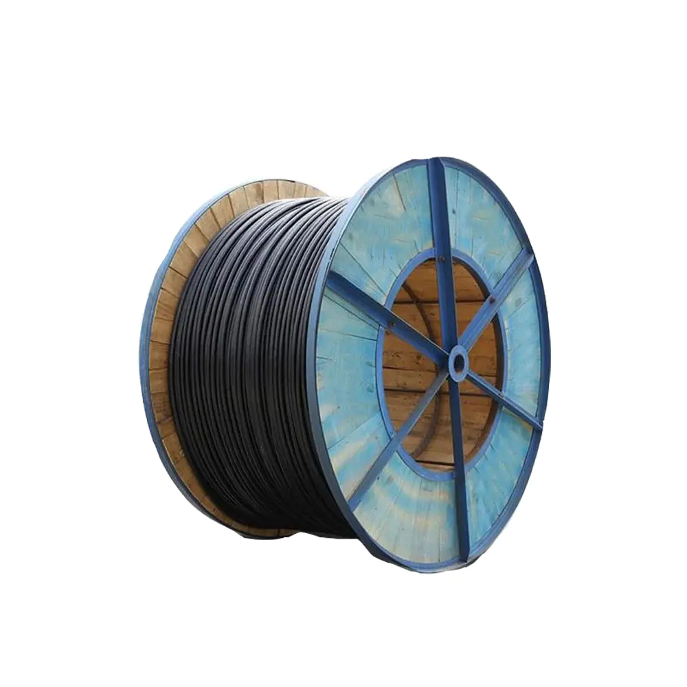
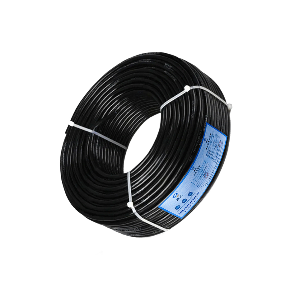
JF(JBF)Strong mechanical properties High-Voltage Cable
Electrical cables are often treated as passive components, but in mobile industrial systems they function as mechanical components as well. Every movement places stress on the conductor, insulation, shield, and sheath. Repeated bending can cause conductor fatigue, while twisting can damage the insulation interface or loosen a poorly designed shield. Abrasion can reduce sheath thickness until moisture or chemicals reach the internal layers. Inadequate flexibility can also increase installation forces and create excessive stress at cable glands, connectors, and equipment terminals.
A flexible high-voltage cable must therefore satisfy several requirements at the same time. It must carry current with acceptable voltage drop and thermal performance. Its insulation must withstand the rated electrical stress and maintain insulation resistance over its service life. The sheath must protect the cable from water, oil, sunlight, abrasion, and impact. The overall construction must allow movement without causing rapid deterioration. If electromagnetic compatibility is important, the cable must also include an effective shield with sufficient coverage and continuity.
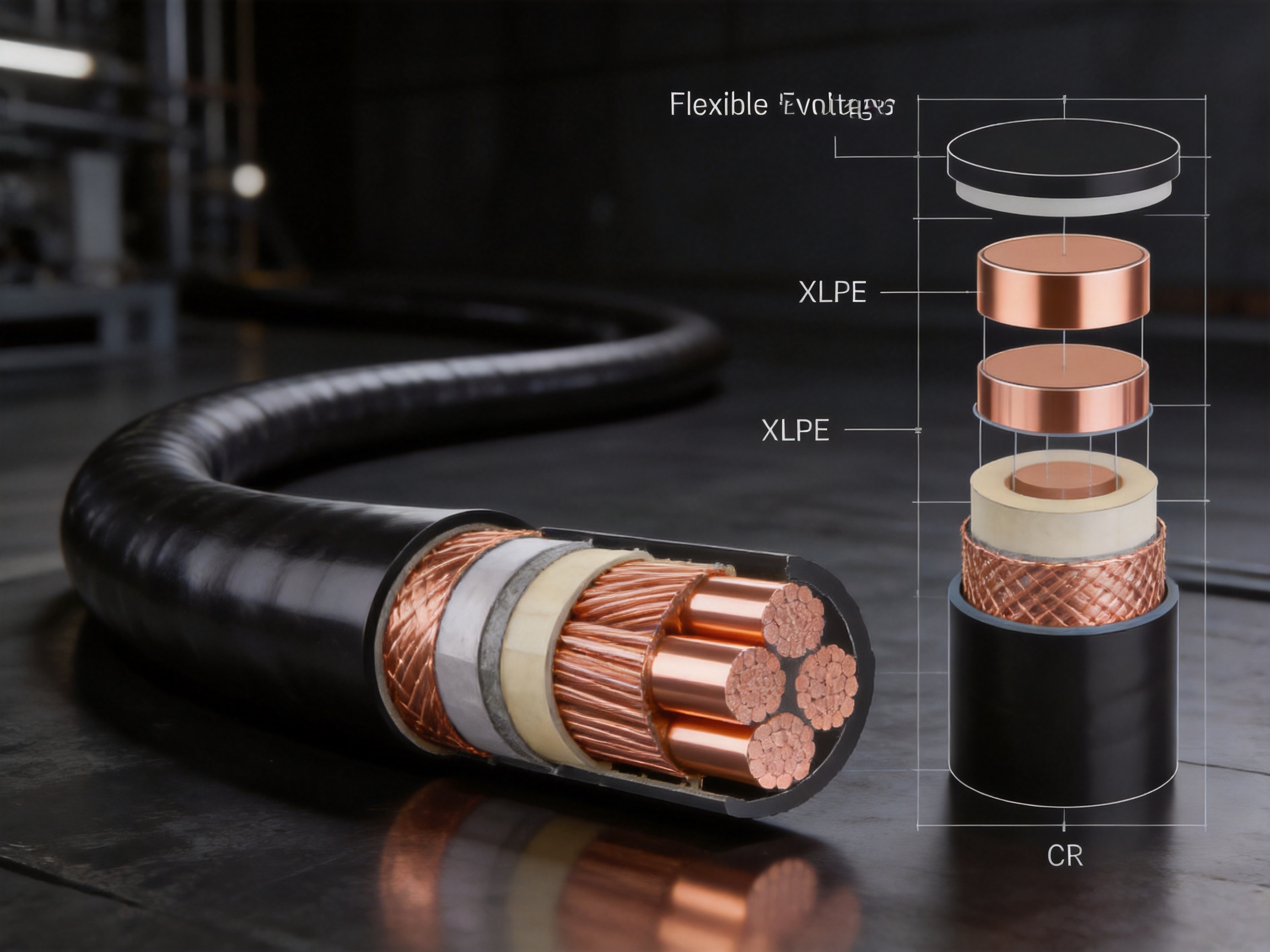
The JF and JBF series address these requirements through a multilayer construction. The copper conductor provides high conductivity and mechanical strength. The insulation system is based on XLPE or EPR, materials selected for their electrical stability and temperature performance. The copper wire braid creates a conductive barrier around the insulated core, helping reduce electromagnetic interference and providing an additional path for fault or induced currents when correctly terminated. The outer CR or CPE sheath protects the cable from the surrounding environment.
This construction is especially valuable where the cable is installed on moving platforms, lifting systems, cranes, mining machines, mobile generators, port machinery, and temporary power equipment. In these applications, cable reliability is determined not only by nominal voltage and current ratings but also by the cable’s ability to tolerate movement and exposure throughout its working life.
The conductor is manufactured from copper and may use a multi-stranded or compacted round construction. Copper provides excellent electrical conductivity, allowing the cable to carry power with relatively low resistive losses. It also offers good solderability, termination compatibility, and practical mechanical strength for industrial cable assembly.
Multi-stranded construction improves flexibility because movement is distributed across many smaller wires instead of being concentrated in one solid conductor. This is important when the cable is routed through a cable carrier, suspended from lifting equipment, or repeatedly bent during operation. Compacted round conductors can provide a more controlled outside diameter and efficient use of internal space while retaining useful flexibility for many installation conditions.
The specified cross-section range of 2.5 mm² to 300 mm² supports a wide variety of applications. Smaller sizes may be used for auxiliary power or compact mobile equipment, while larger sizes are suitable for high-current machinery, generator connections, mining equipment, and temporary power distribution. Final selection must consider current capacity, installation method, ambient temperature, voltage drop, short-circuit conditions, and the number of loaded conductors.
The insulation can be cross-linked polyethylene or ethylene propylene rubber. XLPE is widely recognized for its strong dielectric properties, thermal stability, and relatively low dielectric loss. These characteristics help maintain reliable electrical performance across a broad operating range. EPR provides a rubber-based insulation system with excellent flexibility and resistance to moisture, ozone, and environmental aging.
The insulation material is selected according to the project’s electrical and mechanical requirements. XLPE is suitable where high insulation performance, dimensional stability, and thermal capability are priorities. EPR can be advantageous where flexibility and rubber-like resilience are especially important. Both materials are suitable for industrial cable designs when properly formulated, extruded, cured, and tested.
The standard information specifies insulation thickness in accordance with JB/T 10438 or GB/T 12706.1 requirements. This is important because insulation thickness cannot be chosen only according to a nominal voltage label. The insulation must provide sufficient dielectric strength, withstand test voltage, maintain physical integrity under operating temperature, and remain compatible with the cable’s shielding and sheath layers.
The cable incorporates a copper wire braid shield with coverage of at least 80 percent. Shielding is a major advantage in industrial environments where variable-frequency drives, motors, switching equipment, welding systems, and high-current conductors may generate electromagnetic interference. A continuous and properly terminated braid helps reduce the coupling of unwanted electrical noise into nearby signal and control systems.
The shield also supports safer and more stable system design. When connected according to the electrical system requirements, it can provide a low-impedance path for induced currents or fault-related energy. The final shielding performance depends on braid coverage, braid resistance, termination quality, grounding arrangement, connector design, and installation practice. For this reason, a high-coverage shield should be considered together with the complete cable assembly rather than as an isolated material feature.
Compared with an unshielded flexible power cable, the copper braid provides a clear advantage in installations where power and communication circuits operate close to one another. It can help reduce unplanned equipment behavior, data transmission disturbances, and control-system instability caused by electromagnetic coupling.
The outer sheath is manufactured from chloroprene rubber or chlorinated polyethylene. Both materials are suitable for demanding industrial environments because they can offer a combination of flexibility, oil resistance, abrasion resistance, weather resistance, and mechanical protection.
Chloroprene rubber is valued for its balance of flexibility, resistance to sunlight and weathering, and practical performance in mobile cable applications. Chlorinated polyethylene can provide strong resistance to oils, fuels, chemicals, moisture, and outdoor exposure. The selected sheath formulation may be adjusted according to the equipment environment, required color, mechanical conditions, and customer specifications.
The sheath is available in black, orange, or yellow. Color selection can support cable identification, safety zoning, visibility in work areas, and project-specific installation standards. In addition to visual identification, the sheath serves as the first line of defense against abrasion, contamination, water ingress, and mechanical contact with surrounding equipment.
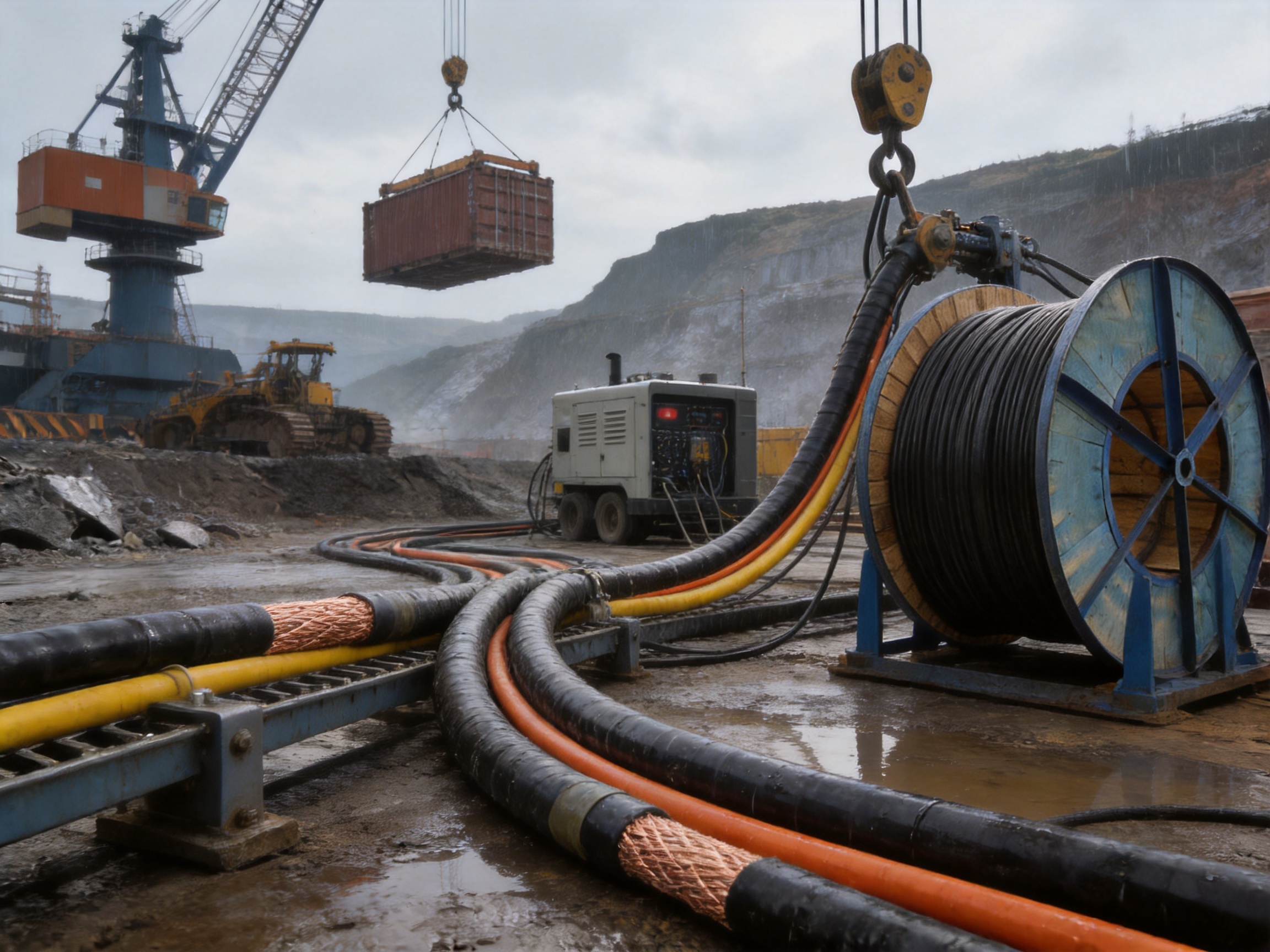
The performance characteristics of the cable are designed to address both electrical safety and mechanical service requirements. The available rated voltages include 450/750 V, 0.6/1 kV, 1.8/3 kV, and 3.6/6 kV. This allows the cable family to cover low-voltage mobile power systems as well as higher-voltage industrial equipment.
The specified test voltage is 3.5U₀ using alternating current for five minutes. This test is used to verify the dielectric integrity of the cable after manufacture. A successful test indicates that the insulation system can withstand a defined electrical stress without breakdown under the specified test conditions. Production testing is an important part of quality control because visual inspection alone cannot confirm internal insulation performance.
Insulation resistance is specified at not less than 500 MΩ·km at 20°C. High insulation resistance helps reduce leakage current and supports safe, stable operation. It also provides a useful indication of insulation quality, cleanliness, moisture control, and manufacturing consistency.
The long-term operating temperature is listed as +90°C for XLPE and +85°C for EPR in the product data. These values must be considered together with the installation method, ambient temperature, current load, ventilation, and grouping conditions. Under short-circuit conditions, the specified conductor temperature can reach up to 250°C for a duration of five seconds. Short-circuit performance depends on conductor area, protective-device clearing time, installation conditions, and the complete electrical system design.
For fixed installation, the minimum bending radius is specified as 10 times the cable outer diameter. For mobile installation, the minimum bending radius is 15 times the cable outer diameter. These values help prevent excessive mechanical stress during routing. In mobile applications, the actual bending path, travel distance, bending frequency, torsion, speed, acceleration, support method, and cable carrier design should also be evaluated.
The minimum installation temperature is listed as -20°C. Installation at temperatures below the recommended limit can make polymeric materials less flexible and increase the risk of sheath cracking or insulation damage. If cold-weather installation is unavoidable, the cable should be handled, stored, and installed according to an approved procedure.
Many standard building wires and fixed-installation power cables are not designed for continuous movement. They may have adequate electrical capacity but lack the conductor stranding, insulation elasticity, and sheath resilience needed for repeated bending. The JF and JBF series are specifically positioned for flexible industrial use, making them better suited to moving equipment and temporary power systems.
The combination of multi-stranded copper, rubber-compatible insulation options, and a flexible protective sheath allows the cable to accommodate movement more effectively than rigid cable constructions. This can simplify installation, reduce terminal stress, and improve operational reliability when the cable is routed through moving machinery.
Industrial cables often encounter oil, fuel, hydraulic fluids, cleaning chemicals, rain, sunlight, dust, and changing temperatures. The CR or CPE sheath is designed to resist these conditions better than ordinary PVC sheaths intended for less demanding environments. The product information specifies resistance to oil, acids, alkalis, and organic solvents, together with strong weather resistance.
The cable also passes an IRM 902 oil immersion test at 70°C for 24 hours and a reciprocating abrasion test of at least 5,000 cycles. These test references provide evidence that the outer materials are intended for practical industrial exposure rather than only clean indoor installation. Actual service performance will depend on chemical concentration, exposure duration, temperature, mechanical contact, and installation conditions, but the design offers a stronger starting point than general-purpose cable.
Unshielded power cables can become sources of electromagnetic interference, particularly when used with motor drives, switching power supplies, generators, and high-current equipment. The minimum 80 percent copper braid coverage in this product family helps contain and reduce electromagnetic coupling.
This feature can be particularly valuable in automated plants, port equipment, mining systems, and generator installations where power cables are routed close to sensors, communication cables, control circuits, and computer systems. Shielding cannot replace correct grounding, separation, filtering, or system-level electromagnetic compatibility design, but it provides an important layer of protection.
Temporary power systems are frequently relocated, installed in exposed areas, and subjected to rough handling. A cable intended for these conditions must tolerate repeated deployment and recovery without rapid degradation. Weather-resistant sheath materials and flexible construction help make the cable suitable for outdoor mobile use.
The orange or yellow sheath options can improve visibility around construction areas, ports, mining sites, and temporary power installations. Black sheaths may be preferred for general industrial use or permanent outdoor routing. The ability to select a sheath color supports better cable management and may help reduce trip hazards or accidental equipment contact.
The cross-section range from 2.5 mm² to 300 mm² and the availability of several voltage classes reduce the need to source every cable type from a different supplier. Customers can discuss conductor construction, sheath color, shielding arrangement, and other design details with one manufacturing partner.
Customization is also available for conductor structure and sheath color. For OEM and project applications, this can be expanded through technical consultation based on customer drawings or samples. A customized design may be useful when equipment has limited routing space, unusual bending conditions, specific identification requirements, or a defined connector and termination system.
Mobile electrical equipment requires cables that can withstand movement while maintaining electrical continuity. Examples include mobile power units, industrial vehicles, movable platforms, and equipment used in construction or maintenance operations. The cable can be routed between fixed and moving sections where vibration and repeated bending are expected.
When designing a mobile installation, engineers should establish the cable’s travel path, minimum bend radius, movement frequency, unsupported length, and exposure to impact. Proper strain relief and suitable cable clamps are equally important. The cable should not be forced to absorb tension through its conductor or shield at the termination point.
Lifting machinery often combines high electrical loads with constant movement. Hoists, cranes, lifting platforms, and port handling equipment may require cables to travel vertically, horizontally, or through cable carriers. The cable must withstand repeated bending, vibration, and occasional contact with metal structures.
The flexible conductor and protective sheath support these conditions, while the copper braid can help limit interference near motor controls and sensors. In crane and hoist systems, cable routing must be designed to prevent crushing, excessive twisting, snagging, and uncontrolled loops. The cable’s rated voltage and current must also match the lifting system’s motor and control architecture.
Port machinery is exposed to humidity, salt-laden air, rain, oil, abrasion, and heavy mechanical activity. Equipment may include container handlers, dockside cranes, mobile loading systems, and auxiliary power units. Outdoor weather resistance and oil resistance are important because cable damage can lead to operational delays and safety risks.
The cable’s CR or CPE sheath provides a protective layer for these environments, while the copper braid supports electromagnetic compatibility in installations containing motors, drives, and communication systems. Appropriate end sealing and connector selection are necessary to protect the cable assembly from water ingress at connection points.
Mining environments are among the most demanding cable applications. Equipment may be exposed to dust, water, mud, oil, impact, vibration, and continuous movement. Cable failures can be difficult to access and may interrupt production or create significant safety concerns.
The product’s abrasion resistance, weather resistance, oil resistance, flexible construction, and shielding performance make it suitable for many mobile mining power applications. However, project engineers must verify that the selected cable meets all applicable mining, flame-retardance, intrinsic-safety, and installation regulations for the specific location. The product data states that the cable passes GB/T 19666 Class B and Class C flame-retardant tests, but local regulatory requirements should always be reviewed separately.
Generator sets generate vibration and may be installed outdoors or moved between work locations. Their connecting cables must tolerate engine vibration, oil exposure, temperature changes, and frequent handling. A flexible, oil-resistant, weather-resistant cable can reduce the risk of sheath damage and termination stress.
Temporary power systems used at construction sites, events, emergency facilities, and maintenance projects also benefit from rugged flexible cables. The orange or yellow sheath can support high visibility, while the available voltage classes allow selection for different generator outputs and distribution arrangements.
Industrial automation systems require stable power and reliable signal environments. Although the cable is primarily a power cable, its shielded construction can be advantageous where power routes pass near control and communication equipment. In selected robotic or automated applications, the cable may be used where the movement profile remains within the product’s approved mechanical limits.
For highly continuous robotic torsion or extremely high-cycle drag-chain operation, the complete cable design should be reviewed with the manufacturer. Cable carrier geometry, torsion angle, acceleration, cycle count, and unsupported length can significantly affect service life. The product’s flexibility and mechanical performance provide a useful foundation, but application-specific validation remains essential.
The reliability of a flexible high-voltage cable depends on more than the bill of materials. Conductor preparation, insulation extrusion, curing, shielding, sheath extrusion, dimensional control, electrical testing, and packaging must be managed as one integrated process. Inconsistent concentricity, contamination, poor bonding, uneven braid coverage, or inadequate curing can reduce cable life even when the nominal materials are correct.
Production begins with copper conductor preparation. Copper wires are drawn or selected to meet the required diameter and electrical characteristics, then stranded or compacted according to the target cross-section. For flexible cable, control of strand tension is especially important. Excessive or uneven tension can affect flexibility and produce irregular geometry. Proper lay length and uniform compaction support consistent diameter and mechanical behavior.
The manufacturing facility’s automated production lines support repeatable processing and higher production efficiency. Automation can reduce variation between production batches, improve process monitoring, and support stable output for both standard models and larger project orders. Conductor tensile strength is specified as at least 200 N/mm², providing a reference for mechanical robustness.
XLPE or EPR insulation is applied through controlled extrusion around the conductor. Key process parameters include material temperature, extrusion pressure, line speed, conductor preheating, cooling conditions, and dimensional stability. The objective is to create a continuous insulation layer with consistent thickness and a smooth interface.
For high-voltage products, insulation cleanliness is particularly important. Foreign particles, voids, moisture, and surface damage can become points of electrical stress concentration. Process control and suitable material handling help reduce these risks. Insulation thickness is produced according to the applicable standard requirements, and finished cable sections are evaluated through dimensional and electrical tests.
After insulation, the copper wire braid is applied around the insulated core. Braid angle, wire tension, coverage, and continuity must be controlled to achieve the specified minimum coverage of 80 percent. A loose or uneven braid may reduce shielding effectiveness and create mechanical instability, while excessive tension may reduce flexibility or damage the insulation.
Shielding quality is verified not only by visual inspection but also by checking braid coverage, continuity, and resistance where required. The cable termination design must preserve shield continuity. Poor termination can undermine the benefit of an otherwise well-manufactured braid, particularly in high-frequency or sensitive automation environments.
The CR or CPE sheath is extruded over the shield to provide environmental and mechanical protection. The sheath must maintain uniform thickness and a stable outside diameter while remaining flexible enough for movement. Temperature control and cooling are important because improper processing can cause surface defects, dimensional instability, or reduced material performance.
Color formulation is controlled according to the selected black, orange, or yellow finish. A consistent surface helps with identification and inspection. The finished sheath is examined for scratches, pinholes, lumps, cracks, and other defects that could affect service performance.
Quality assurance combines electrical, dimensional, mechanical, and environmental evaluation. The specified AC test voltage of 3.5U₀ for five minutes verifies dielectric withstand. Insulation resistance testing at 20°C verifies the electrical condition of the insulation. Dimensional inspection confirms conductor area, insulation thickness, shield structure, sheath thickness, and overall diameter.
Mechanical and environmental checks include oil immersion testing at 70°C for 24 hours, reciprocating abrasion testing of at least 5,000 cycles, tensile evaluation, and flame-retardance testing according to GB/T 19666 Class B and Class C requirements. These tests help ensure that the cable is not evaluated only as an electrical conductor but as a complete industrial product.
Testing and documentation are particularly important for OEM customers and engineering contractors. Product test reports, traceability records, inspection results, and warranty support for standard models can help customers integrate the cable into their quality systems. For customized products, the inspection plan can be aligned with the agreed technical specification.
Anhui Zhishang Cable Technology Co., Ltd. integrates cable research and development, manufacturing, sales, and technical support. The company operates a production base of approximately 5,000 square meters and has more than 50 employees, including quality engineers and research and development technicians with more than 10 years of industry experience.
The company reports more than 10 automated production lines and monthly output of up to 10 million meters. This production capacity supports both routine order fulfillment and larger industrial projects. Standard products may be stocked for fast shipment, while customized products generally require a lead time of approximately 7 to 20 days, depending on construction complexity, material availability, testing requirements, and order quantity.
One important strength is the ability to support OEM and ODM development based on customer drawings or samples. Cable specifications are often closely connected to equipment design. A customer may need a particular conductor layout, sheath color, outer diameter, shielding structure, temperature class, or terminal compatibility. A manufacturer that can review drawings and translate them into a controlled production specification can reduce communication gaps between the cable and equipment teams.
The company’s stated quality philosophy emphasizes quality orientation, integrity, and stability. Its product approach includes full-core, full-length, pure copper specifications, product test reports, and warranty support for standard cable models. These commitments are relevant to customers that need predictable electrical performance and consistent supply rather than only the lowest initial purchase price.
The supplier also serves international markets, including the United States, Canada, Australia, Japan, and parts of Eurasia. International supply requires attention to packaging, documentation, technical communication, production consistency, and delivery coordination. Customers should still confirm the standards and approvals required in their own country and application before placing an order.
| Item | Specification |
|---|---|
| Product series | JF and JBF flexible high-voltage cable |
| Conductor | Copper conductor, multi-stranded or compacted round |
| Cross-section range | 2.5 mm² to 300 mm² |
| Rated voltage | 450/750 V, 0.6/1 kV, 1.8/3 kV, and 3.6/6 kV |
| Test voltage | 3.5U₀ AC for five minutes |
| Insulation | Cross-linked polyethylene or ethylene propylene rubber |
| Insulation standard reference | JB/T 10438 or GB/T 12706.1 requirements |
| Shield | Copper wire braid, coverage of at least 80 percent |
| Sheath | Chloroprene rubber or chlorinated polyethylene |
| Flame retardance | Passes GB/T 19666 Class B and Class C flame-retardant tests |
| Insulation resistance | At least 500 MΩ·km at 20°C |
| Long-term operating temperature | +90°C for XLPE; +85°C for EPR |
| Short-circuit temperature | Up to 250°C for five seconds |
| Minimum bending radius | 10 times cable diameter for fixed installation; 15 times cable diameter for mobile installation |
| Installation temperature | Not lower than -20°C |
| Oil resistance | IRM 902 oil immersion test at 70°C for 24 hours |
| Abrasion resistance | Reciprocating abrasion test of at least 5,000 cycles |
| Weather resistance | Suitable for outdoor use |
| Conductor tensile strength | At least 200 N/mm² |
| Sheath colors | Black, orange, or yellow |
Cable selection should begin with the electrical load. The required conductor cross-section depends on continuous current, permissible temperature rise, installation method, ambient temperature, grouping, voltage drop, and short-circuit protection. The rated voltage must be equal to or greater than the system voltage, and the cable’s insulation system must be suitable for the operating environment.
The movement profile is equally important. Engineers should document whether the cable will remain fixed, move occasionally, travel continuously in a cable carrier, hang vertically, bend in a single plane, or experience torsion. The stated minimum bending radius should be treated as a limit, not as a target for aggressive routing. A larger bending radius generally reduces mechanical stress and can improve service life.
Environmental exposure should be reviewed in detail. Oil, fuel, hydraulic fluid, cleaning chemicals, salt spray, ultraviolet radiation, water, dust, and abrasive surfaces can affect sheath selection. Where exposure is severe, the chemical composition, temperature, concentration, and contact duration should be provided to the manufacturer for confirmation.
Shielding requirements should be established at the system level. Customers should identify whether the cable is installed near variable-frequency drives, servo motors, radio systems, sensitive sensors, data cables, or control electronics. The grounding method, shield termination, connector arrangement, and separation distance should be specified together with the cable.
Finally, customers should confirm documentation requirements. These may include routine test reports, material declarations, flame-retardance results, dimensional drawings, packaging standards, certificates, labeling, and batch traceability. Early confirmation of these requirements can reduce delays during procurement and project acceptance.
The cable should be stored in a clean, dry location away from direct sunlight, sharp objects, chemicals, and excessive heat. Cable drums should be supported properly and rotated only according to the manufacturer’s handling instructions. The cable should not be dragged over rough ground or pulled across sharp edges because damage to the sheath may occur before installation.
During installation, the cable should be unwound from the drum in the correct direction and without creating reverse bends. The specified minimum bending radius must be maintained, especially near glands, connectors, entry points, and moving transitions. Cable clamps should support the cable without crushing the sheath or restricting natural movement.
In a cable carrier, the cable should have sufficient free space and should not be forced against neighboring cables. The carrier should be designed for the cable’s outside diameter, weight, bend radius, and travel speed. Cables intended for movement should not be installed under constant tension unless the application has been specifically designed for that condition.
Shield termination should be short, secure, and compatible with the system grounding design. A long pigtail may increase high-frequency impedance and reduce shielding effectiveness. The connection should be protected against moisture and mechanical loosening, especially in outdoor and mobile equipment.
Before energizing the cable, installers should inspect the sheath for cuts, compression marks, cracks, or other damage. Electrical tests should be performed according to the project’s inspection plan. After commissioning, periodic inspection should focus on areas exposed to repeated movement, oil, abrasion, heat, and mechanical contact.
Electrical safety begins with correct product selection and continues through installation, protection, grounding, and maintenance. The cable must be used within its rated voltage, temperature, current, bending, and environmental limits. Protective devices should be coordinated with the cable’s conductor size and short-circuit capability.
The stated flame-retardant performance under GB/T 19666 Class B and Class C testing supports use in projects that require improved resistance to flame propagation. Customers should verify whether their application requires additional low-smoke, halogen-free, toxicity, fire-resistance, or vertical flame requirements. Not every flame-retardant classification is equivalent to every local building or industrial code.
The product information describes a safe and environmentally responsible design direction, including low-smoke, halogen-free, and flame-retardant characteristics for applicable product types. Because cable materials and constructions can vary by order, customers should request confirmation of the exact environmental and fire-performance properties for the selected model before approval.
Responsible manufacturing also includes efficient material use, process control, reduced waste, and durable products that do not require frequent replacement. A cable with better resistance to abrasion, oil, and weather may reduce maintenance interruptions and premature disposal. The supplier’s focus on automated production, product testing, and customized design supports a more controlled approach to manufacturing quality.
The strongest competitive advantage of this cable family is its combination of electrical capability and mechanical resilience. Many competing products may offer one or two of these characteristics but not all of them in a single construction. An ordinary flexible cable may not provide sufficient voltage capability. A high-voltage cable designed for fixed installation may not withstand repeated movement. An unshielded cable may be unsuitable near sensitive control systems. A cable with a general-purpose sheath may deteriorate quickly in oil or outdoor environments.
The JF and JBF series are positioned between these limitations by combining high-voltage insulation options, flexible copper conductors, high-coverage copper braid shielding, and robust CR or CPE sheathing. The result is a cable family suitable for applications where electrical reliability, movement, and environmental resistance must be considered together.
Another advantage is specification flexibility. The available sizes, voltage classes, sheath materials, colors, and conductor structures allow the cable to be adapted to different equipment designs. This is particularly valuable for manufacturers that require repeatable cable specifications across several machine models or for engineering contractors managing projects with different power levels.
Supplier capability also influences competitiveness. A manufacturer with research and development personnel, automated lines, testing resources, standard inventory, and OEM/ODM support can respond more effectively than a trading company that only resells generic cable. Technical communication, sample review, drawing confirmation, production control, and after-sales support all contribute to total project value.
The cable is suitable for mobile electrical equipment, lifting machinery, port machinery, mining equipment, generator sets, temporary power systems, and other indoor or outdoor applications that require flexibility, shielding, oil resistance, abrasion resistance, and weather resistance.
The listed ratings are 450/750 V, 0.6/1 kV, 1.8/3 kV, and 3.6/6 kV. The correct rating should be selected according to the system voltage, grounding arrangement, transient conditions, and applicable standards.
Yes. The product is designed for flexible and mobile applications. However, the movement pattern must remain within the approved limits. Installation should respect the minimum bending radius, and highly dynamic applications should be reviewed with the manufacturer for travel distance, cycle frequency, torsion, speed, and cable carrier conditions.
The copper braid helps reduce electromagnetic interference and can provide a conductive path for induced or fault-related currents when correctly grounded and terminated. It is especially useful near motors, inverters, generators, sensors, communication cables, and industrial control systems.
XLPE is commonly selected for strong dielectric performance, thermal stability, and dimensional consistency. EPR offers rubber-like flexibility and good resistance to moisture and environmental aging. The final choice depends on voltage, temperature, flexibility, chemical exposure, and project requirements.
The sheath materials are designed for oil resistance, and the product information specifies passing an IRM 902 oil immersion test at 70°C for 24 hours. Customers should provide details of the specific oil, fuel, hydraulic fluid, temperature, and exposure duration when the environment is especially severe.
Yes. The listed sheath colors are black, orange, and yellow, and the conductor structure can be customized according to requirements. Other design details may be reviewed through OEM or ODM development based on drawings, samples, and technical specifications.
The specified minimum bending radius is 10 times the cable outer diameter for fixed installation and 15 times the cable outer diameter for mobile installation. A larger radius may be appropriate for high-cycle movement or severe torsion.
The technical information includes AC withstand testing at 3.5U₀ for five minutes, insulation resistance of at least 500 MΩ·km at 20°C, oil immersion testing, abrasion testing, flame-retardance testing, dimensional inspection, and mechanical evaluation. The exact test documentation should be confirmed for each order.
Customized products typically require approximately 7 to 20 days, depending on the design, materials, quantity, testing, and production schedule. Standard products may be available from stock for faster shipment.
Yes. The sheath provides strong weather resistance and the product is suitable for outdoor mobile use. Outdoor installations should still include appropriate protection at cable ends, connectors, glands, and transition points to prevent water ingress and mechanical damage.
Customers should provide voltage rating, conductor cross-section, number of cores, current requirement, insulation preference, shield requirement, sheath material, color, cable length, movement conditions, environmental exposure, applicable standards, packaging requirements, and expected delivery schedule. Drawings or samples are useful for customized development.
The JF and JBF series flexible high-voltage cables are engineered for industrial applications where ordinary fixed-installation cable may not provide sufficient flexibility, environmental resistance, or electromagnetic protection. Their combination of copper conductors, XLPE or EPR insulation, copper wire braid shielding, and CR or CPE sheath supports reliable use in mobile equipment, lifting machinery, ports, mines, generator systems, temporary power networks, and demanding outdoor installations.
The product’s principal advantages include a wide voltage and cross-section range, flexible construction, high-coverage shielding, resistance to oil and abrasion, strong weather performance, flame-retardant testing, and support for customized conductor and sheath configurations. These advantages are reinforced by the manufacturer’s integrated research, production, testing, and technical service capabilities.
For customers seeking a dependable industrial cable, the most important step is to match the product to the complete application rather than selecting only by conductor size. Voltage, current, bending, torsion, temperature, chemical exposure, grounding, shielding, installation method, and regulatory requirements should all be reviewed. With appropriate selection and installation, this cable family can provide a stable and durable connection for demanding high-voltage mobile power systems.
1. JB/T 10438, technical requirements for relevant rubber-sheathed flexible cable products.
2. GB/T 12706.1, power cables with extruded insulation and rated voltages up to and including 1 kV.
3. GB/T 19666, general rules for flame-retardant and fire-resistant wire and cable products.
4. International Electrotechnical Commission, guidance on power cable construction, electrical testing, and installation practices.
5. Cable manufacturer technical data for JF and JBF flexible high-voltage cable series.
6. Industrial cable engineering practices for mobile machinery, cable carriers, lifting equipment, and outdoor power systems.
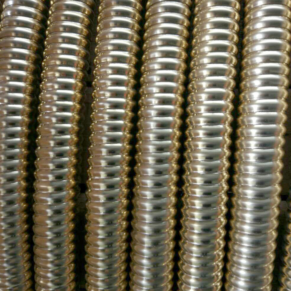
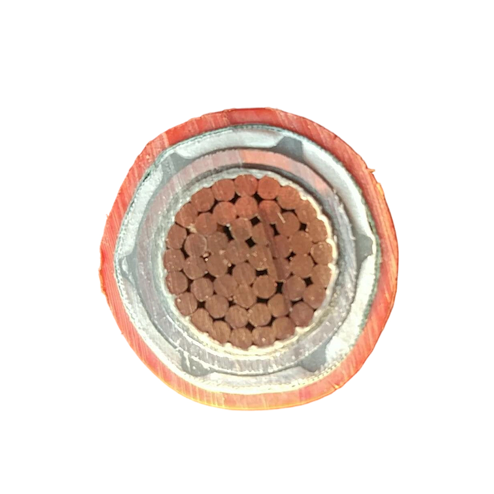
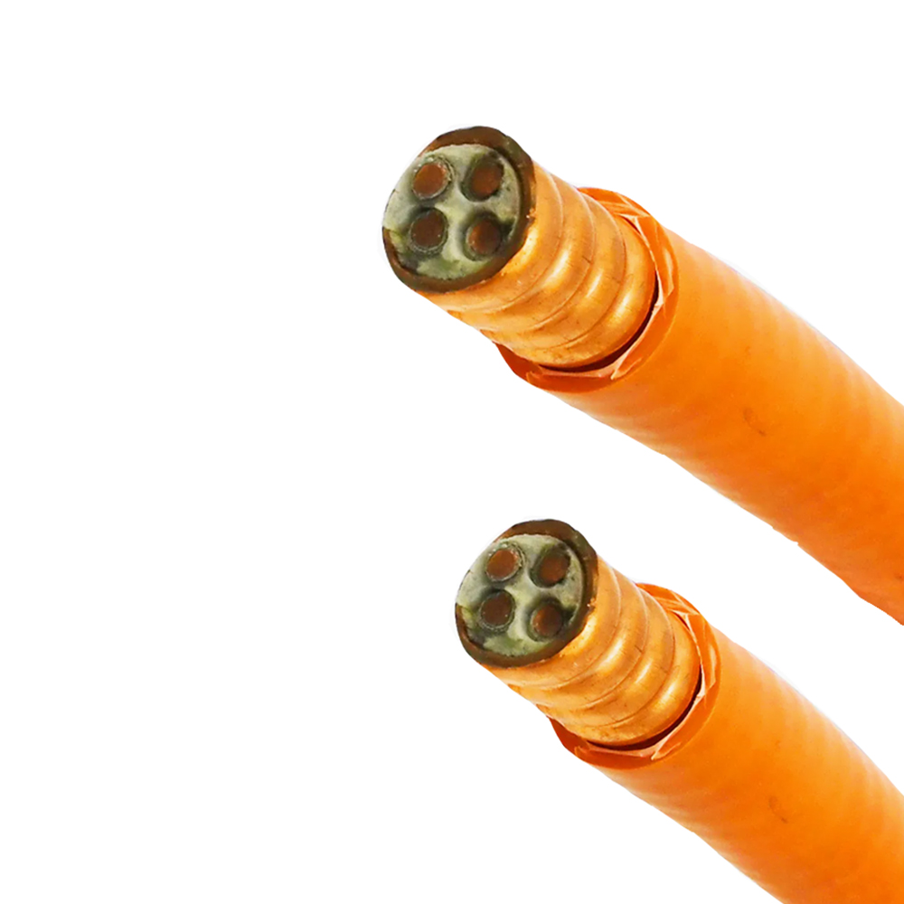
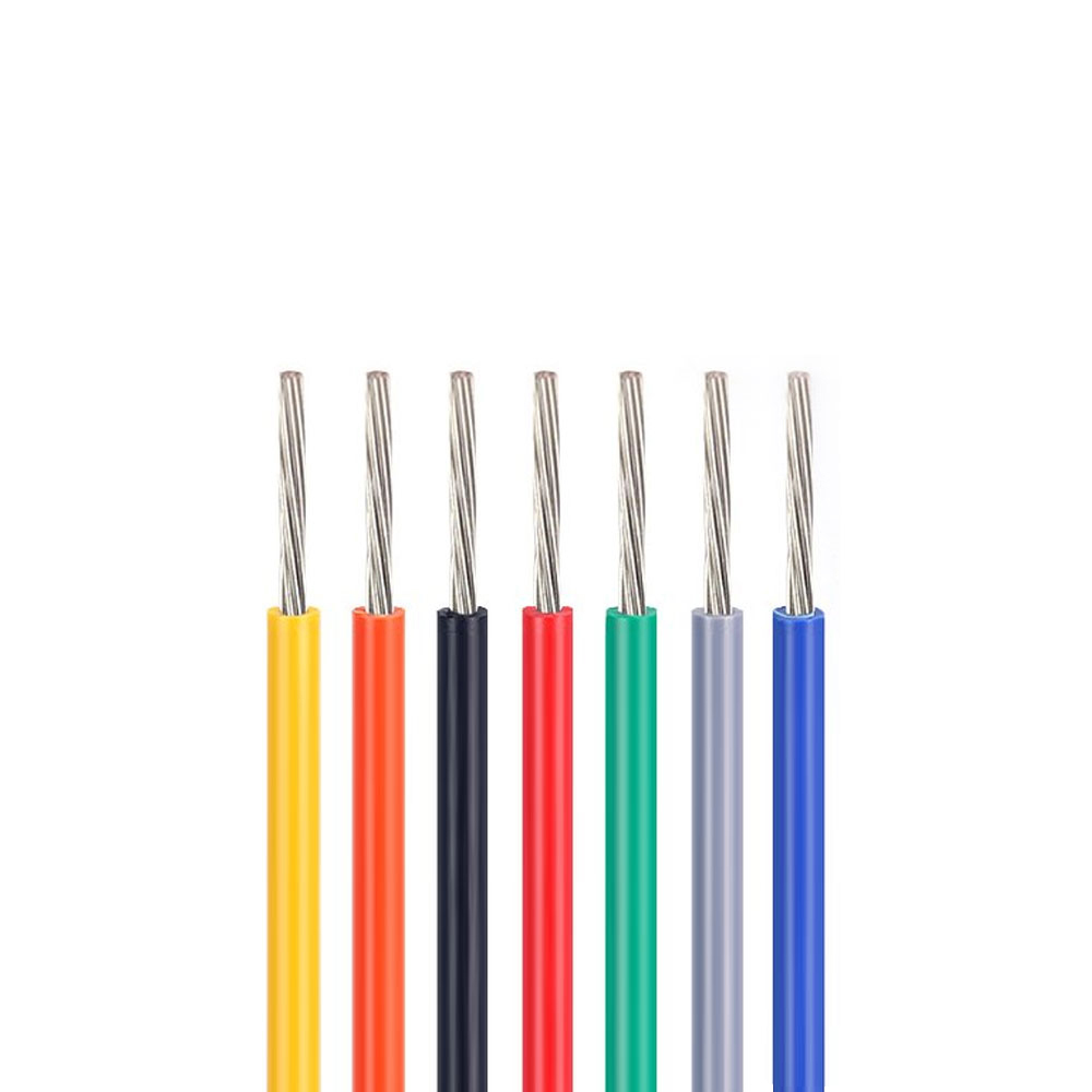

We firmly believe that good cables are not only a competition of materials, but also a reflection of craftsmanship, quality, and responsibility.

Links
Product
Send Inquiry
No. 29 Sankeshu Road, Xuanzhou District, Xuancheng City, Anhui Province, China
+86-18621104555/+86-563-2622999
 Electrical Cable Manufacturer
OEM/ODM Wire and Cable Solutions
 English
 Español
 عربى
 русский