
Get more content that can help you
Content
Modern buildings, industrial facilities, transportation systems, data centers, laboratories, and infrastructure projects depend on stable signal transmission. Control commands, monitoring data, fire alarm signals, emergency broadcasts, building automation messages, and equipment feedback must travel through increasingly complex electromagnetic environments. At the same time, cable systems are expected to meet strict requirements for flame retardancy, smoke suppression, environmental safety, flexibility, service life, and installation reliability.
WDZB1-RYJYSP and WDZB1N-RYJYSP building wires are designed for applications where ordinary control cable or conventional communication cable may not provide sufficient protection. Their construction combines fine-stranded copper conductors, twisted-pair geometry, individual pair shielding, overall shielding, irradiated cross-linked insulation, and a halogen-free low-smoke flame-retardant outer sheath. The WDZB1N-RYJYSP version additionally provides fire-resistant performance for circuits that must continue operating during a fire emergency.
This combination creates a specialized cable solution for low-voltage signal transmission in locations where interference control and fire safety are equally important. Instead of relying on a single protective measure, the design uses several coordinated layers. The twisted-pair structure reduces electromagnetic coupling, the individual shield limits crosstalk between pairs, the overall shield resists external interference, and the flame-retardant and fire-resistant properties help protect the cable system during a fire event.
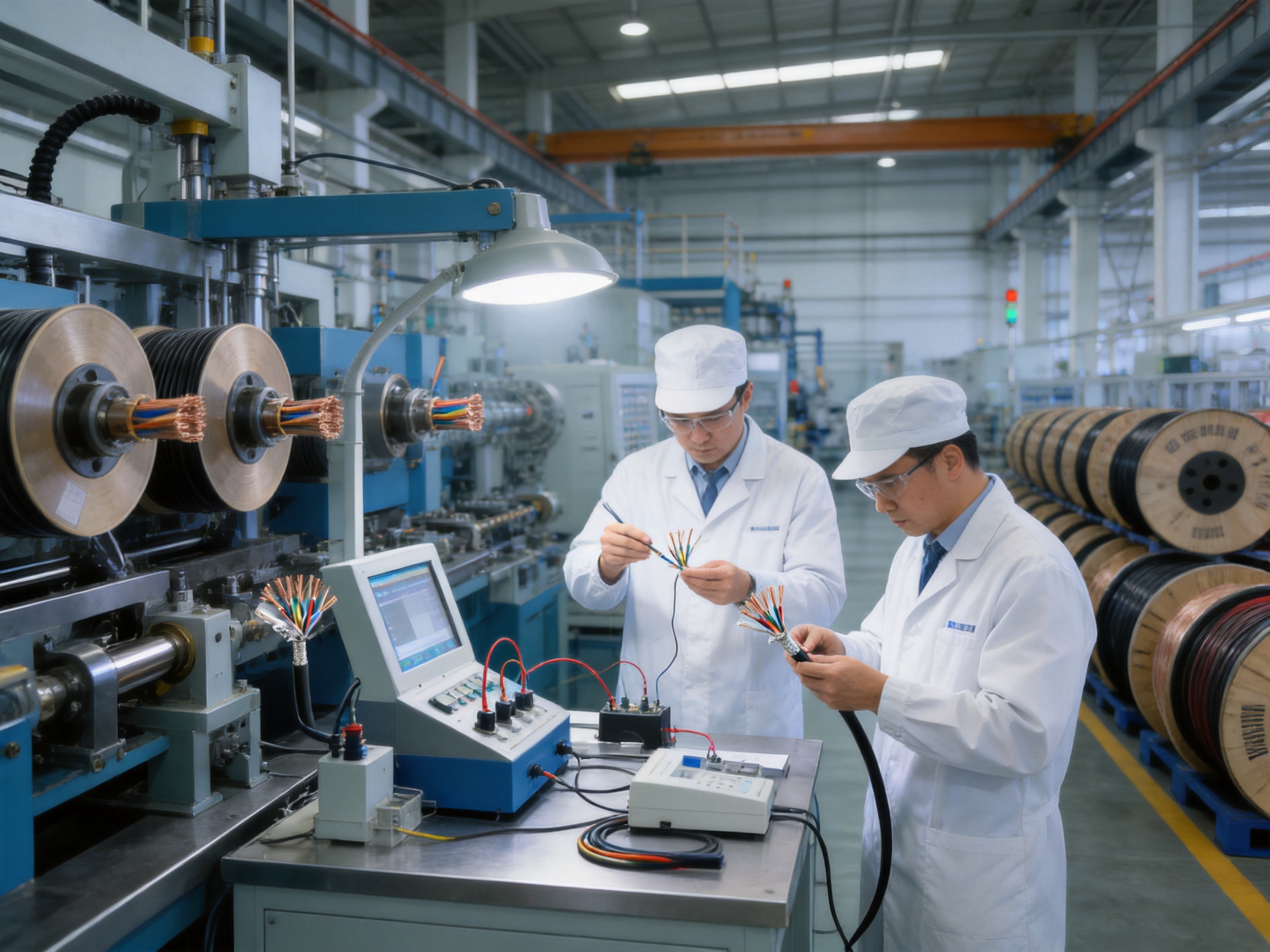
The product is manufactured by Anhui Zhishang Cable Technology Co., Ltd., a Chinese cable producer that integrates research and development, manufacturing, quality control, and technical support. The company operates a modern production base of approximately 5,000 square meters, uses automated production lines, and supports both standard products and OEM or ODM cable development. These capabilities are particularly valuable for project customers that require customized conductor sizes, pair configurations, shielding arrangements, sheath colors, markings, packaging, or documentation.
WDZB1-RYJYSP is a halogen-free, low-smoke, Class B1 flame-retardant, shielded twisted-pair building wire. WDZB1N-RYJYSP uses the same fundamental construction while adding a fire-resistant function. The cable is intended primarily for signal transmission, control circuits, monitoring networks, building automation systems, and other low-voltage applications rather than conventional high-power distribution.
The designation communicates several important characteristics. The WDZB1 portion identifies a halogen-free, low-smoke cable with Class B1 flame-retardant performance. The RYJYSP portion indicates a flexible irradiated cross-linked polyethylene cable with shielding and a twisted-pair structure. The additional N in WDZB1N-RYJYSP identifies the fire-resistant version.
Depending on the applicable product specification, project documentation, and ordering configuration, the rated voltage may be identified as 300/500 V or 300/300 V. The supplied technical information includes both values, so purchasers should confirm the exact rated voltage stated on the quotation, technical datasheet, test report, and cable marking before approval. This verification is important because signal cables can be manufactured for different system classes and installation requirements.
The cable is especially suitable for projects where signal integrity must be maintained in the presence of motors, variable-frequency drives, switching equipment, power cables, communication equipment, medical devices, industrial automation systems, or other sources of electromagnetic disturbance. It is also appropriate where building regulations or project specifications require halogen-free, low-smoke, flame-retardant materials.
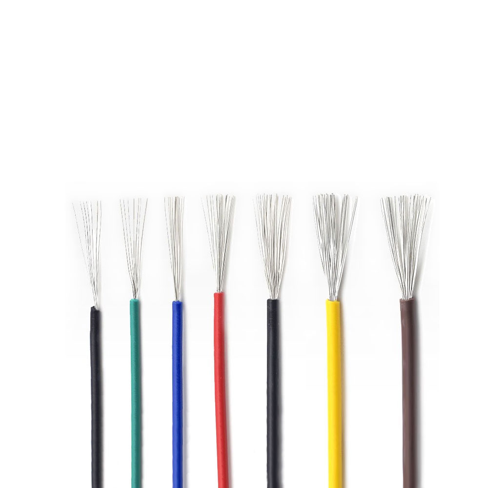
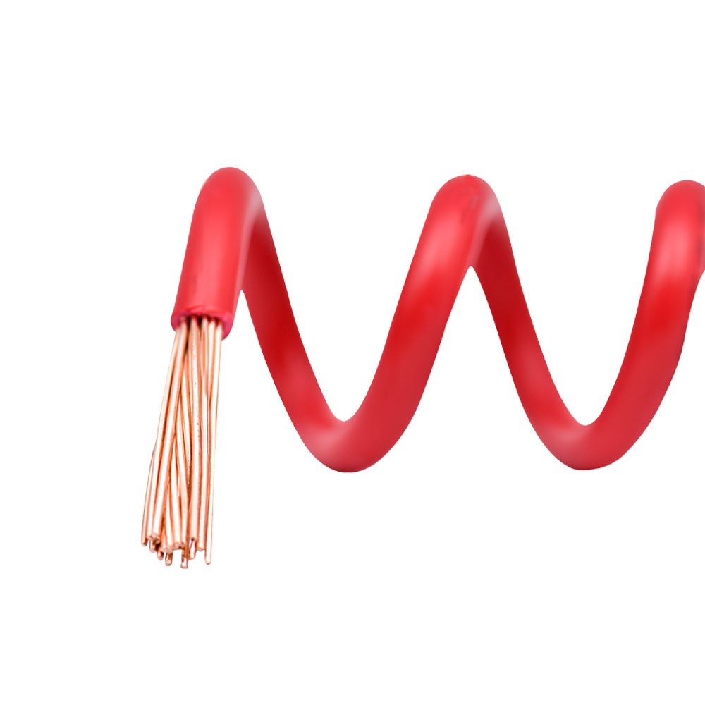
The conductors use annealed copper strands, typically Class 5 or higher, to provide flexibility and reliable electrical conductivity. Fine stranding allows the cable to bend more easily than a solid-core or coarsely stranded conductor. This is useful in control cabinets, equipment connections, raised floors, cable trays, conduit routes, and complex building pathways.
Common conductor cross-sections range from approximately 0.5 mm² to 2.5 mm², although the final size should be selected according to current, voltage drop, transmission requirements, mechanical conditions, and applicable standards. Smaller cross-sections are often appropriate for instrumentation and signal circuits, while larger sizes may be selected for control circuits with greater current demand or longer cable runs.
Using pure copper conductors provides lower resistance and more predictable electrical behavior than copper-clad aluminum alternatives. In signal systems, conductor consistency is important because changes in resistance, impedance, or contact quality can reduce signal reliability. The company's standard production philosophy emphasizes full-core and full-length pure copper specifications for applicable products.
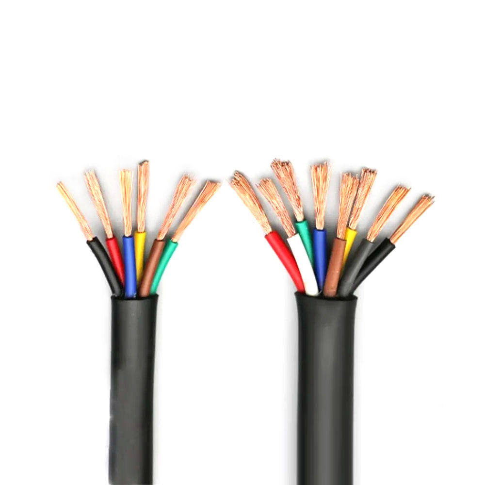
The insulated conductors are twisted together in pairs with a controlled lay length. Twisting causes external electromagnetic fields to affect both conductors in a more balanced way. When the receiving equipment measures the voltage difference between the two conductors, common-mode interference can be reduced.
Pair twisting also helps limit interference between adjacent circuits. A controlled and consistent twist pitch contributes to stable electrical characteristics, repeatable capacitance, and improved signal balance. For communication and automation applications, these details can be more important than simply selecting a cable with a larger conductor.
Different pairs may use different twist lengths to reduce the possibility of repetitive coupling between pairs. The exact construction depends on the number of pairs, required impedance, bandwidth, shielding design, and customer specification. For high-speed or protocol-sensitive systems, the finished cable should be evaluated as a complete assembly rather than judged only by conductor size.
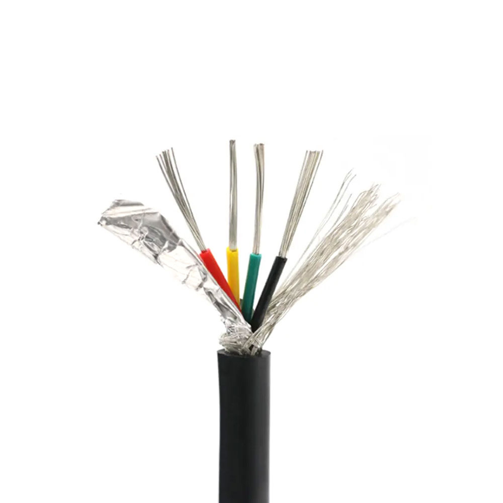
Each twisted pair is typically wrapped with aluminum-plastic composite tape or another suitable shielding layer. Individual pair shielding creates a barrier around the signal conductors and reduces alien crosstalk between neighboring pairs. It is particularly useful when several control or communication channels share the same cable.
This construction offers an advantage over cables that provide only an overall shield. An overall shield can reduce external interference, but it does not always prevent one internal pair from affecting another. By protecting each pair separately, the cable creates a more controlled transmission environment for multiple signals.
Pair shielding must be correctly bonded, overlapped, and connected according to the product design. Installation teams should follow the manufacturer's instructions for drain wires, grounding points, termination hardware, and shield continuity. Poor termination can reduce the benefit of an otherwise high-performance shielded cable.
A second shielding layer surrounds all pairs. This may consist of braided copper, aluminum-plastic composite tape, or a combined structure with a drain wire. The overall shield helps protect the complete cable from external electromagnetic fields generated by power circuits, motors, inverters, transformers, relays, and switching devices.
Copper braid offers mechanical strength, flexibility, and a low-resistance path for shield currents. Aluminum-plastic tape provides broad coverage and effective high-frequency screening when properly installed. Some configurations combine different shielding methods to balance coverage, flexibility, grounding performance, and cost.
The use of both individual pair shielding and overall shielding is one of the product's principal competitive advantages. A basic unshielded twisted-pair cable may be adequate in a quiet office environment, but it may be less reliable near industrial equipment or dense electrical infrastructure. A cable with only an overall shield may still allow internal pair-to-pair interference. The dual-shield arrangement provides more comprehensive protection.
The insulation and sheath use irradiated cross-linked polyethylene, or XLPE, in the product description. Cross-linking improves resistance to heat, aging, and deformation compared with many conventional thermoplastic materials. The long-term operating temperature is specified as 90°C, subject to the exact construction, installation method, and applicable standard.
The outer sheath protects the cable from abrasion, moisture, ultraviolet exposure, and general environmental stress. This makes the cable suitable for demanding indoor routes and selected outdoor applications where the cable is not exposed to conditions beyond its rated design. For outdoor or underground use, the project designer should still evaluate water ingress, mechanical impact, sunlight intensity, soil chemistry, rodents, temperature extremes, and required additional protection.
Cross-linked materials are dimensionally stable over a broad operating range. They are less likely to soften under heat than ordinary non-cross-linked insulation. This contributes to long-term reliability in equipment rooms, ceiling spaces, industrial control areas, and routes where ambient temperature may rise during continuous operation.
The WDZB1 product family is described as meeting Class B1 flame-retardant requirements under GB 31247. This classification evaluates cable combustion behavior through factors such as heat release, flame spread, smoke production, burning droplets, and toxicity-related performance. The supplied information associates this level with high-end building fire protection requirements and describes it as comparable in positioning to the B1ca level used in European cable classification discussions.
Classification systems are not automatically interchangeable. Project engineers should verify the exact test basis, declaration, certificate, and assessment method required by the destination country or project authority. Nevertheless, the product's Class B1 positioning demonstrates that it is intended for applications with more demanding fire-performance expectations than ordinary general-purpose cables.
The cable is designed to resist flame propagation and reduce the contribution of the cable itself to fire development. This is particularly important in cable trays, risers, shafts, suspended ceilings, raised floors, and densely packed equipment spaces where a cable fire could spread along a route.
WDZB1N-RYJYSP adds fire-resistant performance to the Class B1, halogen-free, low-smoke construction. The supplied specification identifies a 750°C/90-minute fire-resistance test under GB/T 19666. The purpose of this design is to help maintain circuit continuity for a specified period during fire exposure, provided that the complete installation system, including supports, joints, terminations, and connected equipment, is suitable for the same requirement.
Fire resistance is different from flame retardancy. Flame retardancy limits flame spread and combustion behavior, while fire resistance focuses on continued electrical operation under fire conditions. A fire-resistant signal cable may be used for emergency communication, fire alarm loops, emergency broadcasting, life-safety monitoring, smoke control systems, evacuation signaling, or other critical circuits, depending on the design approval.
Maintaining circuit integrity requires correct installation. Excessive bending, unsuitable clips, mechanical damage, poor jointing, or incorrect termination can compromise fire-resistant performance. For this reason, the cable should be installed in accordance with the approved project method statement and the manufacturer's technical recommendations.
When halogen-containing cable materials burn, they may release corrosive and irritating gases. These gases can damage electronic equipment and create additional hazards for occupants and emergency responders. Halogen-free materials are intended to reduce such risks.
The cable is described as halogen-free, low-smoke, and low-toxicity. The supplied technical information references GB/T 17650.2 and GB/T 17651.2 and identifies a light transmittance value of at least 80 percent for smoke performance. Reduced smoke can help preserve visibility in escape routes and improve the working conditions of emergency personnel.
These properties are especially valuable in data centers, hospitals, laboratories, airports, stations, underground facilities, public buildings, and high-occupancy spaces. In such environments, the consequences of smoke and corrosive gases may be more serious than the direct flame damage to the cable itself.
Although halogen-free cable improves fire safety, it should not be treated as fireproof under all conditions. Correct circuit design, separation of power and signal routes, fire stopping, equipment protection, emergency planning, and building-level fire systems remain essential.
WDZB1-RYJYSP WDZB1N-RYJYSP Building Wire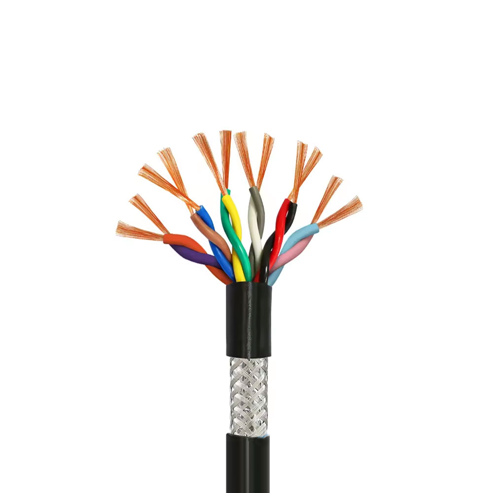
The product can be understood as using four complementary defenses against interference. First, the twisted-pair construction improves balance and reduces susceptibility to external fields. Second, individual pair shielding limits crosstalk between adjacent signal pairs. Third, the overall shield protects all pairs from external electromagnetic energy. Fourth, the controlled manufacturing process helps maintain consistent geometry and electrical performance from one cable length to the next.
The fire-retardant and low-smoke materials provide a separate safety layer rather than an electromagnetic layer. Together, these features create a cable intended for environments where signal reliability and fire performance must be considered at the same time.
Crosstalk occurs when energy from one circuit couples into another. In a building automation system, crosstalk can appear as unstable sensor readings, false control commands, communication errors, intermittent alarms, or unexplained equipment behavior. The risk increases when many circuits are placed in a confined pathway or when signals operate close to high-current switching circuits.
Individual pair shielding helps reduce coupling between pairs, while controlled twist geometry improves balance. The overall shield adds protection against external sources. The result is more robust than a simple parallel conductor arrangement and may be better suited to dense signal infrastructure.
The supplied data identifies stable characteristic impedance, with an example of 100 ohms plus or minus 15 percent. This type of impedance is commonly associated with balanced differential transmission systems. Stable impedance helps reduce reflections, particularly when the cable is connected to equipment and connectors designed for the same electrical characteristic.
The cable is described as capable of supporting digital signal transmission at rates such as 100 Mbps, 1 Gbps, and beyond. Actual performance depends on conductor dimensions, pair geometry, total cable length, connector quality, grounding, installation practice, protocol requirements, and electromagnetic conditions. Customers should request application-specific transmission data when using the product for high-speed communication.
Parameters such as insertion loss, return loss, near-end crosstalk, far-end crosstalk, attenuation-to-crosstalk ratio, and shielding effectiveness should be considered for demanding networks. A product that performs well in laboratory testing may deliver poorer results if it is excessively bent, untwisted at the termination, installed beside high-power equipment, or connected with incompatible components.
The supplied information describes high-frequency shielding attenuation, with an example exceeding 90 dB at 1 GHz. Such values must be confirmed against the actual product configuration and test method. Shielding effectiveness can vary according to braid coverage, tape overlap, grounding arrangement, frequency, cable length, connector design, and installation quality.
For best results, shield continuity should be maintained through the complete transmission path. In some systems, the shield is grounded at one end to reduce low-frequency ground loops; in other high-frequency or industrial installations, both-end bonding may be required. The correct method depends on the system architecture and the equipment manufacturer's requirements.
Unshielded control cable is economical and suitable for many low-interference applications. However, it may be more vulnerable to electromagnetic noise and pair-to-pair coupling. WDZB1-RYJYSP provides a twisted-pair structure, individual pair shielding, and overall shielding, giving it a stronger position in industrial automation, transportation, medical, and data-processing environments.
The shielded design can help reduce troubleshooting caused by unstable analog values, communication interruptions, false alarms, or control errors. It also allows designers to use a single structured cable solution for multiple low-voltage signals where separate unshielded cables might require greater physical separation.
A cable with only an overall shield may offer protection from external interference but does not fully isolate the internal pairs. In high-density signal applications, internal crosstalk can remain a concern. The product's individual pair shields add another barrier, improving separation among circuits.
This dual-shield construction can be especially useful when a single cable carries several data channels, sensor circuits, control signals, or communication pairs. It may also simplify route planning in facilities where available pathways are limited.
Ordinary PVC cable remains widely used because it is cost-effective and easy to process. However, PVC-based products may not satisfy project requirements for halogen-free construction, low smoke, low toxicity, or advanced flame performance. The WDZB1 family is intended for projects where these factors have a higher priority.
The use of irradiated cross-linked polyethylene also supports a higher-temperature operating environment and improved aging resistance. This can contribute to longer service life when the cable is exposed to heat, repeated operation, or demanding installation conditions.
Some fire-resistant cables provide circuit integrity but may not offer the same combination of pair-level shielding, overall shielding, flexible fine-stranded conductors, and halogen-free low-smoke construction. WDZB1N-RYJYSP is positioned as a signal cable that combines these features in one product family.
For critical systems, this reduces the need to choose between fire performance and signal integrity. The appropriate selection still depends on the required circuit function, fire duration, voltage, data rate, mechanical installation, and approval requirements.
Feature |
WDZB1-RYJYSP |
WDZB1N-RYJYSP |
Typical Conventional Signal Cable |
Primary function |
Low-voltage signal and control transmission |
Signal and control transmission with fire resistance |
General signal or control transmission |
Conductor |
Fine-stranded annealed copper |
Fine-stranded annealed copper |
Solid or stranded conductor, depending on type |
Pair structure |
Twisted pairs |
Twisted pairs |
May be twisted or parallel |
Pair shielding |
Individual pair shielding |
Individual pair shielding |
Often unavailable |
Overall shielding |
Copper braid or composite shield |
Copper braid or composite shield |
May be unshielded or single-shielded |
Insulation and sheath |
Irradiated cross-linked, halogen-free material |
Irradiated cross-linked, halogen-free material |
Often conventional thermoplastic material |
Flame performance |
Class B1 flame retardant |
Class B1 flame retardant |
Varies by product |
Fire resistance |
Not the primary function |
Specified fire-resistant version |
Varies by product |
Environmental profile |
Halogen-free, low-smoke, low-toxicity |
Halogen-free, low-smoke, low-toxicity |
Depends on material selection |
Data centers contain dense racks, power distribution equipment, cooling systems, backup generators, uninterruptible power supplies, and high-speed communication infrastructure. These systems generate potential electromagnetic interference and create strict fire-safety requirements.
WDZB1-RYJYSP can be used for selected monitoring, building management, equipment feedback, access control, environmental sensors, and low-voltage communication applications. The shielded twisted-pair construction can support stable signal transmission in areas where power and data infrastructure are installed close together.
WDZB1N-RYJYSP may be considered for critical alarm or emergency circuits where continued operation during a defined fire exposure period is required. The final application must be confirmed by the data center fire strategy and system designer.
Hospitals require reliable communication among monitoring systems, nurse call systems, building automation controls, medical equipment interfaces, fire alarm networks, and emergency systems. Signal disruption can affect operational efficiency and, in some cases, safety-related functions.
Halogen-free, low-smoke materials are valuable in occupied medical spaces because smoke and corrosive gases may threaten patients, visitors, staff, and sensitive electronic equipment. The low-voltage, shielded construction is suitable for selected signal routes, subject to medical electrical system requirements and local regulations.
Laboratories often use precision instruments, automated sampling systems, environmental controls, sensors, and specialized equipment. Small changes in signal quality can influence measurement stability or equipment operation.
The cable's pair-level shielding and overall shielding can help protect low-level signals from interference generated by motors, pumps, heaters, laboratory automation, and switching devices. Its flexible construction also supports installation around equipment and within restricted pathways.
Factories contain motors, drives, contactors, robotic systems, programmable controllers, industrial networks, and sensors. These devices can generate both radiated and conducted electromagnetic noise. Cables are frequently routed through cable trays and control cabinets with limited separation between signal and power circuits.
The product can be used for sensor signals, control commands, equipment feedback, industrial buses, and building-to-machine communication links when the electrical characteristics match the protocol requirements. Its flexible conductor and multiple shielding layers can simplify installation in complex industrial routes.
Tunnel monitoring, transportation control, ventilation systems, emergency communications, signaling, and utility corridor sensing require dependable low-voltage connections over long and sometimes inaccessible routes. These environments may include moisture, mechanical vibration, electromagnetic interference, and high consequences for service interruption.
The product's weather-resistant cross-linked sheath and low-smoke fire performance make it suitable for selected indoor, semi-outdoor, tunnel, and infrastructure applications. Designers should confirm whether additional waterproofing, armored protection, conduit, or mechanical safeguards are required.
Modern commercial buildings integrate access control, lighting management, energy monitoring, HVAC control, fire alarm systems, emergency broadcast, occupancy sensors, and intelligent building platforms. These systems depend on reliable signal pathways distributed across floors, plant rooms, risers, and equipment spaces.
WDZB1-RYJYSP can support structured low-voltage control and monitoring networks. Its Class B1 flame-retardant positioning and halogen-free construction may help satisfy green building, public safety, and project material requirements.
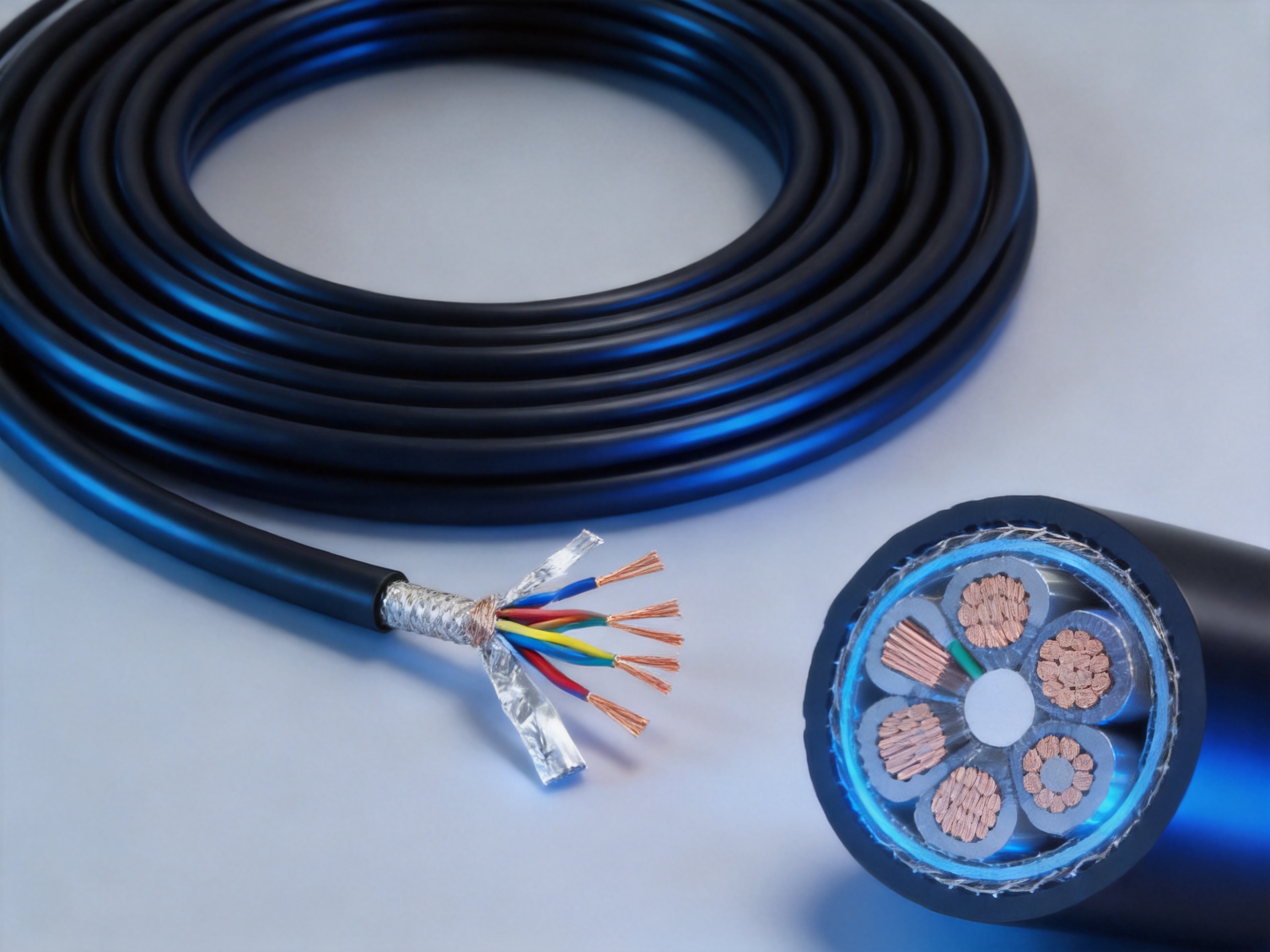
Anhui Zhishang Cable Technology Co., Ltd. integrates product research, production, sales, and technical service. This structure allows the company to respond to customer requirements without separating product design from manufacturing realities.
For specialized cables, close coordination between engineering and production is important. A change in conductor size may affect impedance. A different shield may affect flexibility. A new sheath material may change diameter, bending radius, and flame performance. Integrated development allows these factors to be reviewed together.
The company operates more than ten automated production lines and reports a monthly output capacity of up to ten million meters. Automated equipment supports consistent conductor stranding, insulation extrusion, pair twisting, shielding application, cabling, sheath extrusion, marking, and take-up.
Automation does not replace engineering judgment, but it can reduce variation in repetitive production steps. Stable line speed, controlled extrusion conditions, consistent twist pitch, and accurate dimensional control are important for maintaining electrical and mechanical properties along the full cable length.
Irradiated cross-linked insulation and sheathing require appropriate material selection and process control. The degree of cross-linking, dimensional stability, surface quality, color consistency, and mechanical performance should be monitored through the production and testing process.
Material control is also essential for halogen-free and low-smoke performance. The insulation and sheath must be formulated as part of the complete cable system rather than treated as separate aesthetic components. Proper compounding helps maintain flexibility, flame performance, aging resistance, and compatibility with extrusion equipment.
Signal cable production depends on accurate pair geometry. If twist pitch changes significantly, electrical balance and impedance may vary. If shielding is applied unevenly, the cable may develop weak points in interference protection. If the overall shield is damaged or has insufficient coverage, high-frequency performance may be reduced.
Manufacturing controls should therefore include conductor resistance checks, insulation dimensional checks, twist and lay verification, shield coverage inspection, sheath diameter control, spark testing, and finished cable electrical testing. These controls support the product's intended performance across the entire reel or drum.
The company emphasizes product test reports, full-core and full-length specifications, and warranty support for standard cable models. For project procurement, customers should request the documents needed for approval, such as technical datasheets, routine test results, type-test information, material declarations, conformity documents, and applicable certification records.
Testing should be matched to the project requirement. Typical checks may include conductor resistance, insulation resistance, withstand voltage, continuity, polarity, dimensional inspection, tensile strength, elongation, aging, flame spread, smoke density, halogen content, fire resistance, and transmission performance.
Not every test applies to every product or market. The customer and manufacturer should agree on the acceptance criteria before production begins. This is especially important for export projects, public infrastructure, and fire-rated systems.
The company supports OEM and ODM development based on customer drawings, samples, or defined technical requirements. Customization may include conductor cross-section, number of pairs, pair identification, shield construction, drain wire, sheath color, printing, packaging, nominal diameter, operating temperature, rated voltage, and fire-performance options.
Customized cables normally require additional engineering review. The company indicates that standard products may be stocked for fast shipment, while customized products typically require approximately seven to twenty days of lead time. Actual lead time depends on raw-material availability, order quantity, testing requirements, production scheduling, and export documentation.
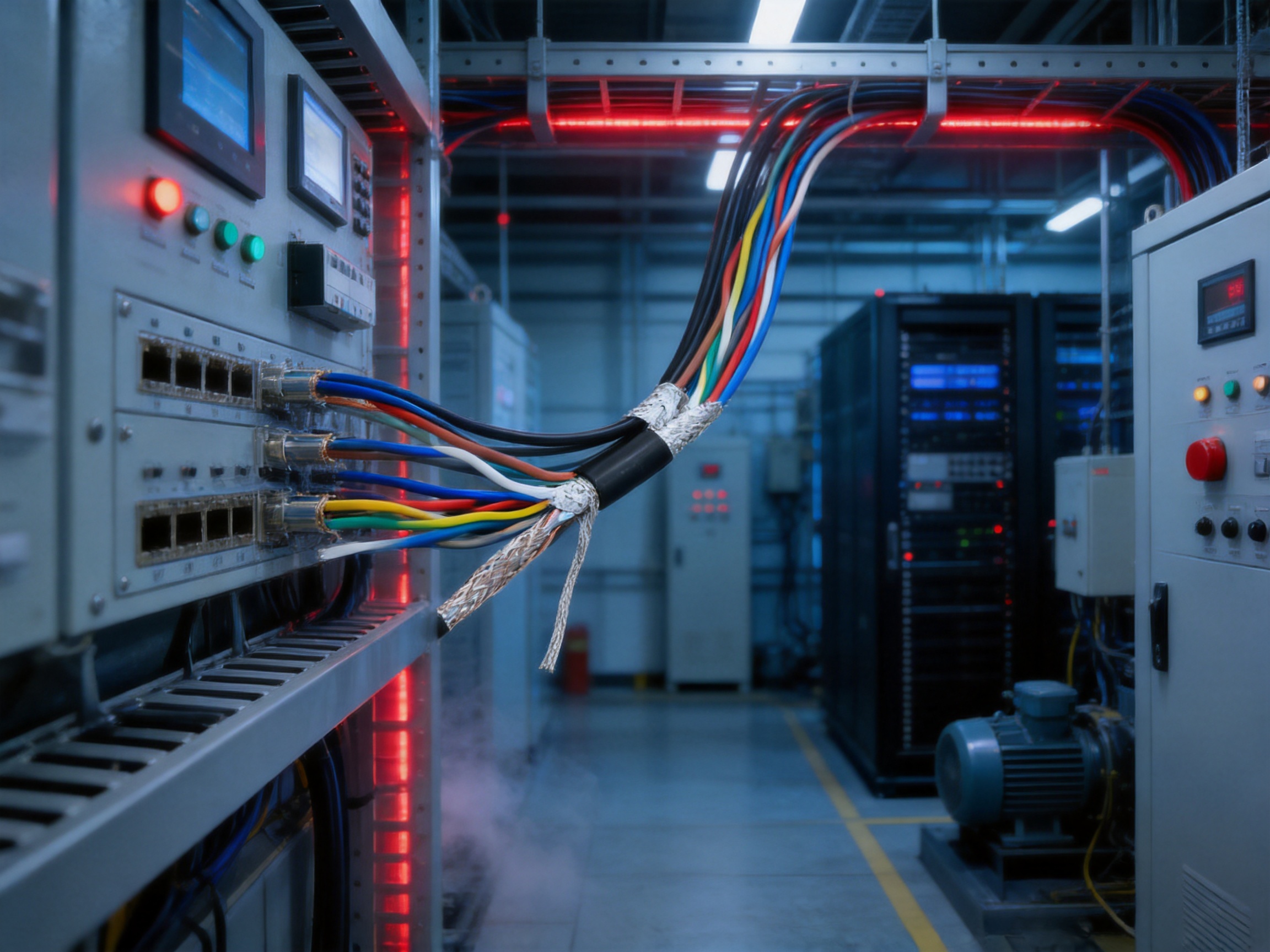
The supplied information identifies a minimum bending radius of at least 15 times the cable diameter. This relatively generous requirement reflects the cable's multi-layer construction, including pair shields and an overall shield. Exceeding the permitted bending limit can deform the pair geometry, damage the shield, increase return loss, or reduce mechanical service life.
Installers should avoid sharp bends, repeated flexing at the same point, forced entry into undersized conduits, and excessive pulling tension. Cable rollers, suitable guides, and correctly sized glands can reduce installation stress.
Shielded cable performance depends on the termination method. Pair shields and overall shields should be connected in accordance with the approved wiring design. Drain wires must be handled carefully and should not be left loose where they could contact unintended circuits.
Grounding arrangements vary by application. Designers should consider signal frequency, equipment grounding, potential differences, lightning protection, and electromagnetic compatibility requirements. A shield that is disconnected, poorly bonded, or terminated with excessive pigtail length may provide less protection than expected.
Even a well-shielded cable should be routed with appropriate separation from high-voltage and high-current circuits. Parallel runs beside motors, inverters, transformers, and switching conductors should be minimized or managed according to project standards. Crossing power cables at right angles can reduce inductive coupling where practical.
Clear marking helps prevent installation errors and simplifies maintenance. Pair numbers, circuit references, destination labels, and shield termination information should be recorded during installation. For fire-resistant circuits, the cable route and support system should also be documented.
The cable should be matched with compatible terminals, connectors, glands, patch panels, and control equipment. A cable may have suitable electrical performance while an unsuitable connector creates excessive reflection, poor shielding continuity, or mechanical damage.
Before specifying WDZB1-RYJYSP or WDZB1N-RYJYSP, project engineers should define the function of the circuit. Is it a sensor loop, a digital communication bus, a building automation network, an emergency broadcast circuit, a fire alarm connection, or a general control line? The answer affects conductor size, pair count, impedance, fire rating, and installation method.
The environmental conditions should then be reviewed. Important factors include indoor or outdoor installation, ambient temperature, moisture, ultraviolet exposure, mechanical impact, vibration, chemical contact, routing length, tray fill, and proximity to power equipment.
Signal requirements should be identified in measurable terms. These may include data rate, frequency range, characteristic impedance, maximum attenuation, crosstalk limits, shielding effectiveness, maximum length, and termination arrangement. If the cable will be used in an established communication system, compatibility with the existing protocol and connectors should be confirmed.
Finally, the required compliance documents should be listed. These may include national standards, fire classification, halogen-free and smoke test results, environmental declarations, inspection reports, factory acceptance test records, and destination-market approvals.
A specialized cable project is rarely solved by selecting a conductor and adding an outer jacket. The conductor, twist geometry, shield arrangement, insulation, sheath, fire performance, diameter, flexibility, and termination method must operate together.
An experienced manufacturer can help translate system requirements into a practical cable design. This can reduce the risk of selecting a product that is electrically acceptable but mechanically unsuitable, or mechanically flexible but unable to meet the required fire or transmission performance.
Anhui Zhishang Cable Technology Co., Ltd. combines production capacity with engineering support. Its production base, automated lines, research and development personnel, and experience in industrial automation, intelligent manufacturing, weak-current engineering, appliance equipment, and power-related applications provide a foundation for project-oriented cable supply.
The company also serves international markets, with products supplied to countries and regions including the United States, Canada, Australia, Japan, and parts of Eurasia. For overseas customers, this international orientation may support communication regarding specifications, packaging, documentation, quality requirements, and shipment planning.
The company's stated business philosophy emphasizes quality, integrity, and stability. In practical terms, these principles should be reflected in traceable raw materials, consistent production, documented testing, responsive technical service, and realistic delivery commitments.
It is primarily used for low-voltage signal, control, monitoring, automation, and communication circuits that require twisted-pair transmission, individual pair shielding, overall shielding, halogen-free materials, low smoke, and Class B1 flame-retardant performance.
WDZB1N-RYJYSP is the fire-resistant version. Both products use a similar shielded twisted-pair construction and Class B1 halogen-free, low-smoke design, while the N version is intended to maintain circuit integrity during a specified fire exposure period according to the applicable test requirement.
The supplied information identifies the WDZB1N-RYJYSP version as meeting a 750°C/90-minute fire-resistance test under GB/T 19666. The exact certificate, test configuration, installation system, and application limitations should be confirmed before use in a life-safety circuit.
Twisting helps balance the two conductors in a pair and reduces susceptibility to external electromagnetic fields. It also contributes to improved control of crosstalk and signal stability.
Individual pair shielding helps prevent interference between pairs, while the overall shield protects all pairs from external electromagnetic interference. The combined structure is more comprehensive than an unshielded or single-shielded design.
The cross-linked sheath provides resistance to moisture and ultraviolet exposure, and the product is described as suitable for selected harsh indoor and outdoor environments. Outdoor use must still be evaluated for water immersion, mechanical impact, sunlight, temperature, rodents, and any additional protection required by the project.
The specified long-term operating temperature is 90°C. The actual allowable temperature depends on conductor size, ambient temperature, installation method, current loading, and the applicable product specification.
The supplied information specifies a minimum bending radius of at least 15 times the cable diameter. Installers should confirm the final value for the ordered construction and avoid sharp bends or repeated flexing.
The product information describes support for digital transmission rates such as 100 Mbps and 1 Gbps or higher. Actual performance depends on the cable configuration, length, connectors, installation, protocol, and electromagnetic environment. Application-specific testing is recommended for critical high-speed systems.
Common signal-oriented sizes are described as approximately 0.5 mm² to 2.5 mm². Other sizes may be possible through customization, subject to engineering review, production feasibility, and minimum order requirements.
Yes. The company supports OEM and ODM development based on customer drawings, samples, or defined technical requirements. Possible options include conductor size, pair count, shielding, sheath color, marking, packaging, and performance requirements.
The company indicates that customized products typically require approximately seven to twenty days of lead time. The final schedule depends on order quantity, raw materials, testing, production planning, and shipping arrangements.
Customers should request the applicable datasheet, product standard, test reports, conformity documents, fire-performance evidence, material declarations, inspection requirements, and packaging details. Export or public-infrastructure projects may require additional certificates.
No. Halogen-free, low-smoke construction reduces smoke and corrosive gas risks, while flame retardancy limits flame spread. It does not eliminate fire risk. Complete safety also requires correct installation, fire stopping, circuit protection, emergency planning, and building fire systems.
The grounding method depends on the system design, signal frequency, equipment requirements, and electromagnetic compatibility strategy. The manufacturer's installation guidance and the equipment supplier's instructions should be followed rather than applying one grounding method to every project.
WDZB1-RYJYSP and WDZB1N-RYJYSP provide a specialized solution for low-voltage signal systems that must operate reliably in demanding electromagnetic and fire-safety environments. Their main strengths are the combination of fine-stranded copper conductors, twisted-pair geometry, individual pair shielding, overall shielding, irradiated cross-linked insulation and sheathing, halogen-free low-smoke materials, and Class B1 flame-retardant performance.
The WDZB1N-RYJYSP version extends this capability with a fire-resistant design intended for critical circuits that require continued operation during a specified fire exposure period. This makes the product family relevant to data centers, hospitals, laboratories, industrial automation facilities, smart buildings, transportation systems, tunnels, utility corridors, and other high-reliability projects.
Compared with conventional unshielded or single-shielded cables, the product offers more comprehensive interference protection. Compared with ordinary thermoplastic cables, it provides a stronger environmental and fire-safety profile. Compared with basic fire-resistant signal cables, it combines circuit protection with a sophisticated shielded twisted-pair structure.
The product's value also depends on the manufacturer's ability to produce consistent cable geometry, control materials, verify performance, customize constructions, and provide appropriate technical documentation. With automated manufacturing lines, research and development capabilities, a modern production facility, and OEM or ODM support, Anhui Zhishang Cable Technology Co., Ltd. is positioned to supply both standard and project-specific cable solutions.
For successful application, engineers should confirm the exact rated voltage, fire classification, transmission requirements, conductor size, bending radius, shield termination, installation conditions, and destination-market compliance documents. When these factors are properly matched, WDZB1-RYJYSP and WDZB1N-RYJYSP can form a dependable part of a safer, more stable, and more resilient low-voltage signal infrastructure.
GB/T 19666, General Rules for Flame Retardant and Fire-Resistant Cables and Wires.
GB 31247, Classification and Test Methods for Burning Behavior of Cables in Building Applications.
GB/T 17650.2, Test on Gases Evolved During Combustion of Materials from Cables.
GB/T 17651.2, Measurement of Smoke Density of Cables Burning Under Defined Conditions.
GA 306, Technical Requirements and Test Methods for Smoke Toxicity and Related Fire-Safety Performance.
International Electrotechnical Commission, guidance on low-voltage cables, conductor classes, insulation systems, and cable testing.
European Committee for Standardization, cable reaction-to-fire classification principles for construction products.
Manufacturer-provided technical information for WDZB1-RYJYSP and WDZB1N-RYJYSP shielded twisted-pair building wires.

We firmly believe that good cables are not only a competition of materials, but also a reflection of craftsmanship, quality, and responsibility.

Links
Product
Send Inquiry
No. 29 Sankeshu Road, Xuanzhou District, Xuancheng City, Anhui Province, China
+86-18621104555/+86-563-2622999
 Electrical Cable Manufacturer
OEM/ODM Wire and Cable Solutions
 English
 Español
 عربى
 русский