
Get more content that can help you
Content
High-voltage power distribution in underground coal mines requires cable systems that can withstand electrical stress, mechanical impact, moisture, corrosive atmospheres, vibration, restricted installation spaces, and demanding fire-safety conditions. A cable that performs well in an ordinary industrial plant may not provide adequate protection in a mine tunnel, vertical shaft, inclined roadway, underground substation, or mobile mining machine. For this reason, mining power cables must combine dependable insulation, controlled electric-field distribution, mechanical protection, flame retardancy, and installation flexibility in one engineered product.
The MYJV, MYJV22, and MYJV32 series are mining cross-linked polyethylene insulated high-voltage power cables developed for these conditions. The product family covers non-armored, steel-tape-armored, and fine-steel-wire-armored structures. Each version is designed for a different installation requirement, allowing users to select a cable according to the level of mechanical protection, tensile strength, movement, and flexibility required by the project.
The series uses copper conductors, XLPE insulation, conductor and insulation shields, and flame-retardant outer sheath materials. Depending on the model, it may also include double steel tape armor or fine steel wire armor. Available voltage ratings range from 3.6/6 kV to 18/30 kV, while conductor cross-sections range from 25 mm² to 500 mm². This makes the product family suitable for a broad range of underground high-voltage distribution and transmission applications.
Manufactured by Anhui Zhishang Cable Technology Co., Ltd., the series reflects an integrated approach covering cable design, conductor processing, insulation extrusion, shielding, armoring, sheath production, testing, and customer-specific engineering support. The manufacturer combines automated production lines, technical personnel, quality control procedures, OEM/ODM capability, and project-based cable selection assistance to provide more than a standard catalog product.
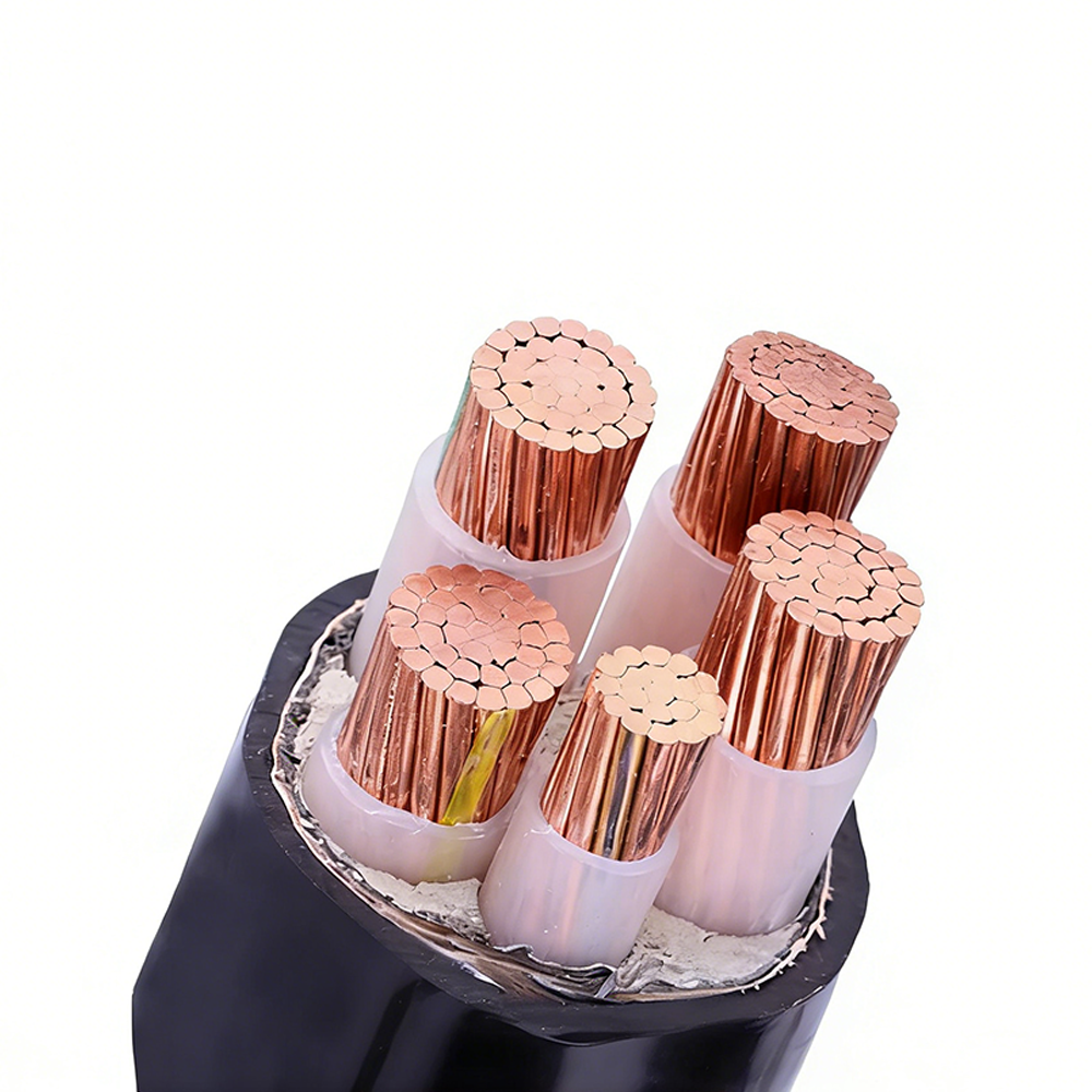
MYJV MYJV22 MYJV32 (Mining Cross-linked High Voltage Cable)
Mining operations depend on continuous electrical power. Underground equipment such as coal shearers, roadheaders, pumps, conveyors, ventilation systems, drainage systems, crushers, hoists, underground substations, and control equipment must operate reliably under conditions that are often more severe than those found above ground. A power interruption can affect productivity, ventilation, worker safety, water management, and the stability of the entire mining operation.
High-voltage cables are used to deliver electrical energy over significant distances while limiting current-related losses. In underground mines, the power system may include surface substations, main underground substations, local distribution stations, long tunnel runs, shaft installations, and mobile equipment connections. Each section can require a different cable construction.
A fixed cable installed in a protected cable tray does not experience the same stress as a cable placed in a roadway exposed to falling rock or vehicle movement. Similarly, a vertical shaft cable must withstand forces caused by its own weight, while a cable connected to a mobile machine must tolerate repeated bending and movement. The MYJV family addresses these differences through construction variants rather than relying on one general-purpose design.
The non-armored MYJV version is intended for fixed installation where the cable is adequately protected from crushing, impact, and other mechanical hazards. MYJV22 adds double steel tape armor for improved resistance to compression and external impact. MYJV32 uses fine steel wire armor to provide higher tensile strength and better suitability for vertical shafts, slopes, and installations involving elevation changes.
For mobile high-voltage applications, the supplied material also identifies an MTJV mobile structure. This design uses flexible conductors and a mobile cable construction intended for equipment such as coal shearers and roadheaders. Although the principal product title refers to the MYJV, MYJV22, and MYJV32 series, the mobile construction is important when selecting a cable family for mining equipment that moves frequently.
The cable uses copper conductors in compacted round or sector-shaped configurations. Copper provides high electrical conductivity, good connection performance, and dependable current-carrying capability. Compaction reduces unnecessary voids between conductor wires, helping control the overall cable diameter and improving the efficiency of subsequent insulation and sheath processing.
The available conductor cross-section range is 25 mm² to 500 mm². This range allows the cable to be matched to different load requirements, transmission distances, installation methods, and voltage-drop limitations. Correct conductor selection should consider continuous operating current, ambient temperature, grouping, installation arrangement, short-circuit conditions, permissible voltage drop, and the electrical characteristics of the complete mine distribution system.
A compacted conductor can also provide a more consistent interface with the conductor shield. This is important in a high-voltage cable because irregularities, air pockets, or sharp protrusions at the conductor-insulation interface can intensify the local electric field. A carefully processed conductor supports more uniform insulation extrusion and contributes to long-term dielectric stability.
The conductor shield is a semi-conductive layer placed around the conductor. Its function is to create a smoother and more controlled electrical transition between the conductor and the main insulation. By reducing localized electric-field concentration, the shield helps limit electrical stress at the conductor surface.
In high-voltage cable design, the conductor shield must maintain close and consistent contact with the insulation. Manufacturing precision is therefore essential. Variations in shield thickness, surface smoothness, adhesion, or concentricity can influence partial discharge performance and the long-term reliability of the cable.
Cross-linked polyethylene is used as the main insulation material. XLPE is widely selected for medium- and high-voltage power cables because it offers a favorable combination of dielectric strength, thermal capability, mechanical stability, and resistance to moisture. It can support higher continuous conductor temperatures than many traditional thermoplastic insulation systems, provided that the complete cable is correctly designed and installed.
The stated long-term operating temperature is from -40°C to +90°C. Under short-circuit conditions, the conductor temperature may reach up to 250°C for a maximum duration of five seconds, subject to the applicable design and installation conditions. The actual permissible short-circuit current depends on conductor size, fault duration, initial temperature, screen and armor design, and the governing technical standard.
XLPE insulation also supports stable electrical performance over long service periods. Its low dielectric losses and strong insulation characteristics are useful in high-voltage networks where the cable may operate continuously under substantial electrical stress. The specified insulation resistance is at least 1000 MΩ·km at 20°C.
The insulation shield consists of a semi-conductive layer applied over the XLPE insulation. Together with the conductor shield, it helps produce a controlled radial electric field within the cable. The insulation shield also provides a defined interface for metallic screening, grounding, or other protective elements included in the complete design.
A stable insulation shield is particularly important in underground mining systems because the operating environment may contain moisture, dust, vibration, and temperature variation. These factors can increase the consequences of manufacturing defects or poor termination practices. The shield structure in this series is intended to support uniform electric-field distribution and reduce the likelihood of partial discharge.
The construction changes according to the model. MYJV is a non-armored version for fixed installation in locations where external mechanical damage is unlikely or where a separate protective system is already provided. MYJV22 uses double steel tape armor, creating an additional barrier against crushing, impact, and certain forms of external attack. MYJV32 uses fine steel wire armor, providing improved tensile strength for shafts, slopes, and other installations in which the cable may be exposed to pulling forces or vertical loads.
The outer sheath is manufactured from flame-retardant PVC or flame-retardant polyolefin, including low-smoke, halogen-free options where specified. The black sheath is suitable for typical industrial and mining environments and provides protection against abrasion, moisture, contamination, and ordinary handling damage.
In an underground mine, the outer sheath is not merely a cosmetic layer. It is the first barrier against water, mud, dust, acidic contaminants, and mechanical contact. A properly selected sheath can help preserve the internal electrical structure and reduce the risk of premature deterioration.
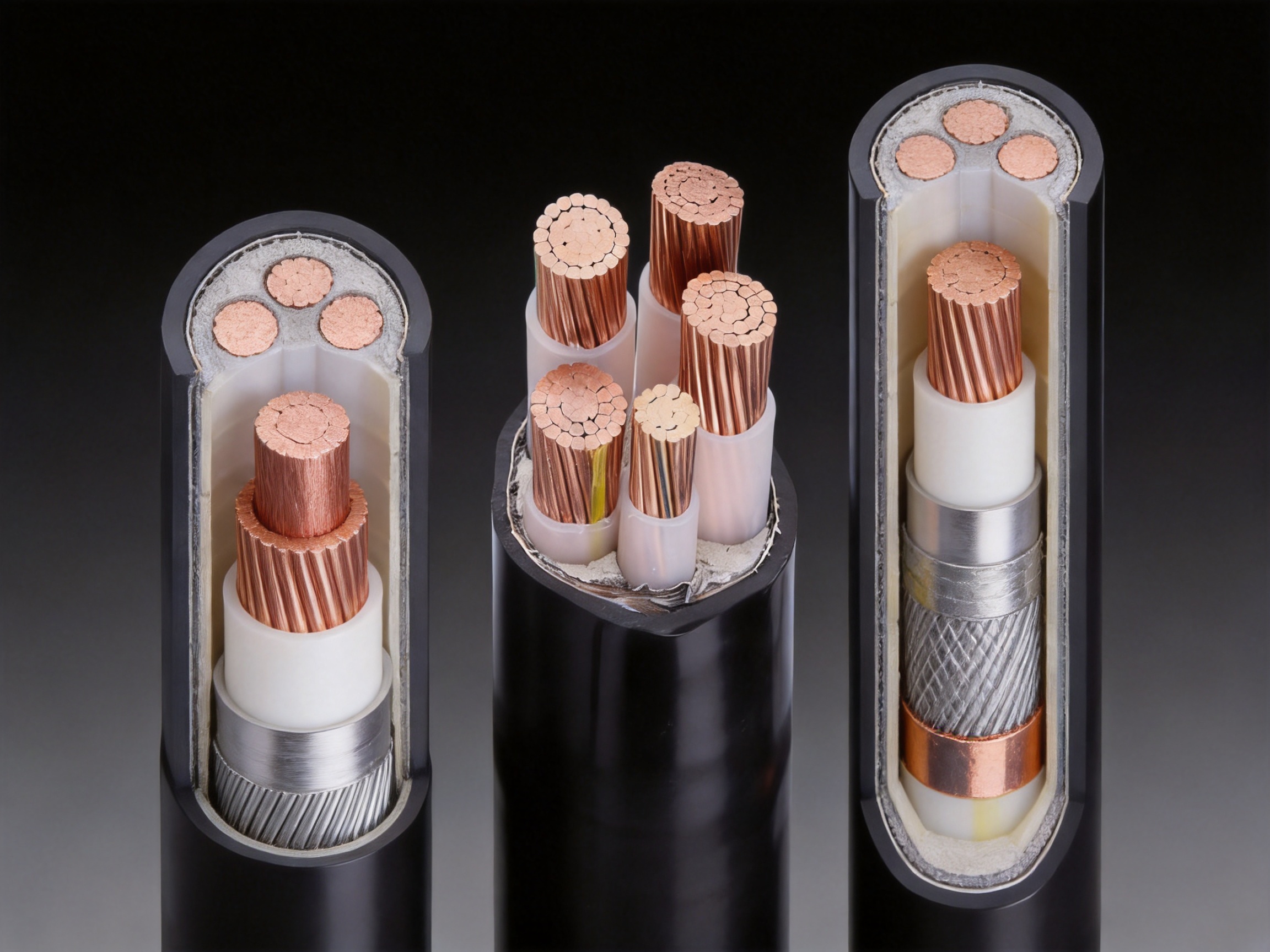
| Model | Main Construction | Primary Strength | Typical Installation |
|---|---|---|---|
| MYJV | Non-armored mining high-voltage cable | Lower weight, easier handling, lower cost | Protected fixed installations, cable trays, and controlled indoor routes |
| MYJV22 | Double steel tape armor | Crush and impact resistance | Tunnels, direct-buried routes, and areas exposed to external mechanical damage |
| MYJV32 | Fine steel wire armor | High tensile strength and improved resistance to pulling forces | Vertical shafts, inclined roadways, and routes with elevation differences |
| MTJV mobile construction | Flexible conductors, mobile metal-shielded structure, no conventional fixed armor | Repeated movement and bending capability | Coal shearers, roadheaders, and other mobile mining equipment |
MYJV is the most lightweight construction in the group. It is suitable when the cable is installed in a protected route and does not require additional armor. Examples may include fixed installation in a controlled cable tray, protected underground electrical room, or enclosed distribution route where the risk of crushing and impact is low.
The lower weight can simplify transportation, pulling, positioning, termination, and maintenance. It may also reduce the supporting requirements of cable trays and other installation structures. Because it does not include armor, the cable can offer a more economical solution for projects that already provide sufficient mechanical protection through the installation environment.
MYJV should not be selected solely because it is lighter or less expensive. The project designer must verify that the installation route genuinely protects the cable from vehicles, falling materials, sharp edges, excessive tension, and other hazards. Where external risk is significant, an armored construction is normally more appropriate.
MYJV22 uses double steel tape armor to improve resistance to compression and impact. This construction is useful in tunnels, direct-buried applications, and fixed routes where the cable may encounter external pressure, accidental contact, or abrasion from surrounding materials.
The armor can help protect the insulated cores from damage caused by localized crushing. It also provides a stronger physical barrier against rodents, insects, and other sources of sheath penetration. In a mine tunnel, where maintenance access may be difficult and cable replacement can interrupt production, this additional protection may contribute to a longer service life.
MYJV22 is especially suitable for general fixed high-voltage distribution where the main concern is external mechanical damage rather than high vertical tension. It is not automatically the best option for every shaft or slope installation, because steel tape armor and fine steel wire armor serve different mechanical purposes.
MYJV32 uses fine steel wire armor to provide higher tensile strength. This makes it appropriate for vertical shafts, inclined roadways, and other routes in which the cable may be pulled, suspended, or exposed to significant height differences.
The wire armor can also improve resistance to torsional deformation compared with an unarmored structure. This is valuable in underground installations where vibration, movement of support systems, or changes in cable routing may place mechanical stress on the cable. Correct support, cleating, bending-radius control, and termination remain essential; armor does not eliminate the need for proper installation engineering.
For a shaft project, selecting a high-tensile cable can reduce the risk of damage caused by the cable's own weight and installation forces. The final design should also include appropriate suspension arrangements, spacing, support calculations, fault-current considerations, and earthing or bonding provisions.
Mobile mining equipment presents a different challenge. A cable connected to a coal shearer or roadheader may be dragged, flexed, twisted, and repositioned repeatedly. A fixed armored cable, even when mechanically strong, may not provide the bending endurance needed for continuous movement.
The MTJV construction described in the supplied technical information uses flexible conductors and a multilayer shielded mobile structure. Its purpose is to accommodate frequent movement while maintaining high-voltage insulation and shielding performance. Flexible conductors reduce bending stress, while the overall cable design is intended to support the dynamic requirements of mining machinery.
Mobile cables must be selected according to the equipment manufacturer's requirements, travel distance, bending path, minimum bending radius, drag-chain or reel arrangement, frequency of movement, and expected torsion. A cable designed for fixed installation should not be substituted for a mobile construction simply because the voltage and conductor size appear similar.
The cable series is available in rated voltage classes of 3.6/6 kV, 6/10 kV, 8.7/15 kV, 12/20 kV, and 18/30 kV. These ratings allow the product to serve different sections of underground mine power systems, from local high-voltage equipment connections to longer distribution and transmission routes.
The selected voltage rating must correspond to the system's nominal voltage, maximum operating voltage, insulation coordination, switching conditions, and applicable electrical regulations. Cable selection should be performed by qualified electrical engineers, particularly where the cable will connect to mining transformers, switchgear, substations, motors, or mobile equipment.
The stated test voltage is based on a power-frequency withstand test of 3.5U0 for five minutes. This test is intended to verify the integrity of the cable insulation system under a specified electrical stress. Testing conditions, test equipment, acceptance criteria, and sampling or routine-test procedures should be confirmed against the applicable standard and purchase specification.
High-voltage testing is one part of a broader quality program. Conductor resistance, dimensional checks, insulation thickness, shield continuity, sheath integrity, insulation resistance, partial discharge, and visual inspection may also be included depending on the cable type, voltage class, order requirements, and applicable certification procedure.
The supplied technical data specifies partial discharge of no more than 10 pC at 1.73U0. Partial discharge is a localized electrical discharge that can occur within insulation defects, voids, interfaces, or areas of excessive electric-field concentration. If not controlled, repeated partial discharge can gradually erode insulation and reduce service reliability.
The product's conductor shield, XLPE insulation, and insulation shield are designed to provide a smooth and uniform electrical system. Manufacturing cleanliness, accurate extrusion, stable material processing, and careful cooling are important to achieving reliable partial discharge performance.
For mining operators, low partial discharge performance can be particularly valuable because underground cable replacement may require extensive shutdowns, specialist labor, ventilation coordination, and restricted-access work. Preventing electrical degradation at the manufacturing stage can therefore support both safety and operating continuity.
Fire safety is a critical requirement in underground mines. The supplied information states that the cables pass MT 818.12 and the GB/T 19666 bundle flame test. Flame-retardant sheath materials are intended to limit flame spread and help reduce the contribution of the cable to a fire event.
Low-smoke and halogen-free materials may be specified where reduced smoke generation and corrosive gas emissions are required. These characteristics can be important in enclosed tunnels and underground rooms, where smoke can obstruct evacuation routes, reduce visibility, and interfere with emergency response.
Flame retardancy does not make a cable fireproof. Proper cable spacing, support, routing, overcurrent protection, termination quality, inspection, and mine-wide fire-prevention procedures remain necessary. The cable is one component of a complete electrical and fire-safety system.
Underground mines frequently contain water seepage, condensation, wet ground, mud, dust, and chemically aggressive substances. The cable's XLPE insulation and flame-retardant sheath are selected to support operation in humid environments. The supplied product information also identifies moisture and corrosion resistance as common advantages of the series.
Moisture resistance depends on the complete construction and installation. Cable ends should be sealed during storage and transportation. Terminations and joints must be installed with compatible components and according to approved procedures. Damage to the sheath should be repaired promptly, and cables should not be left in standing water unless the design and installation method specifically permit it.
Mining cables are exposed to a combination of mechanical stresses rather than one single type of force. These may include crushing by machinery, impact from falling rock, tension during installation, vibration from rotating equipment, torsion caused by movement, abrasion against supports, and repeated bending. The correct construction depends on which stress is most likely to occur.
MYJV22 addresses crushing and impact through double steel tape armor. This makes it a practical option for fixed routes in which the cable may be exposed to external pressure. MYJV32 addresses tensile loads through fine steel wire armor, making it more suitable for vertical or inclined installations. The mobile construction addresses repeated movement through flexible conductors and a dedicated flexible arrangement.
The specified minimum bending radius is 15 times the cable outer diameter for fixed installation and 20 times the cable outer diameter for mobile installation. These values are important during cable pulling, routing, storage, connection, and equipment movement. Bending below the permitted radius can damage the conductor, shield, insulation, armor, or sheath even if no visible defect appears immediately.
For mobile service, the bending-radius requirement should be considered dynamically. The cable may experience a smaller effective radius during machine travel than during initial installation. The movement path should be reviewed for sharp transitions, repeated reverse bending, torsional restraint, dragging over rough surfaces, and contact with hot or abrasive components.
For armored fixed installations, support spacing should prevent excessive sag and local stress. In vertical shafts, the cable-support system must be designed to carry the cable weight and withstand operational vibration. The armor should be properly bonded or treated in accordance with the system grounding design and applicable regulations.
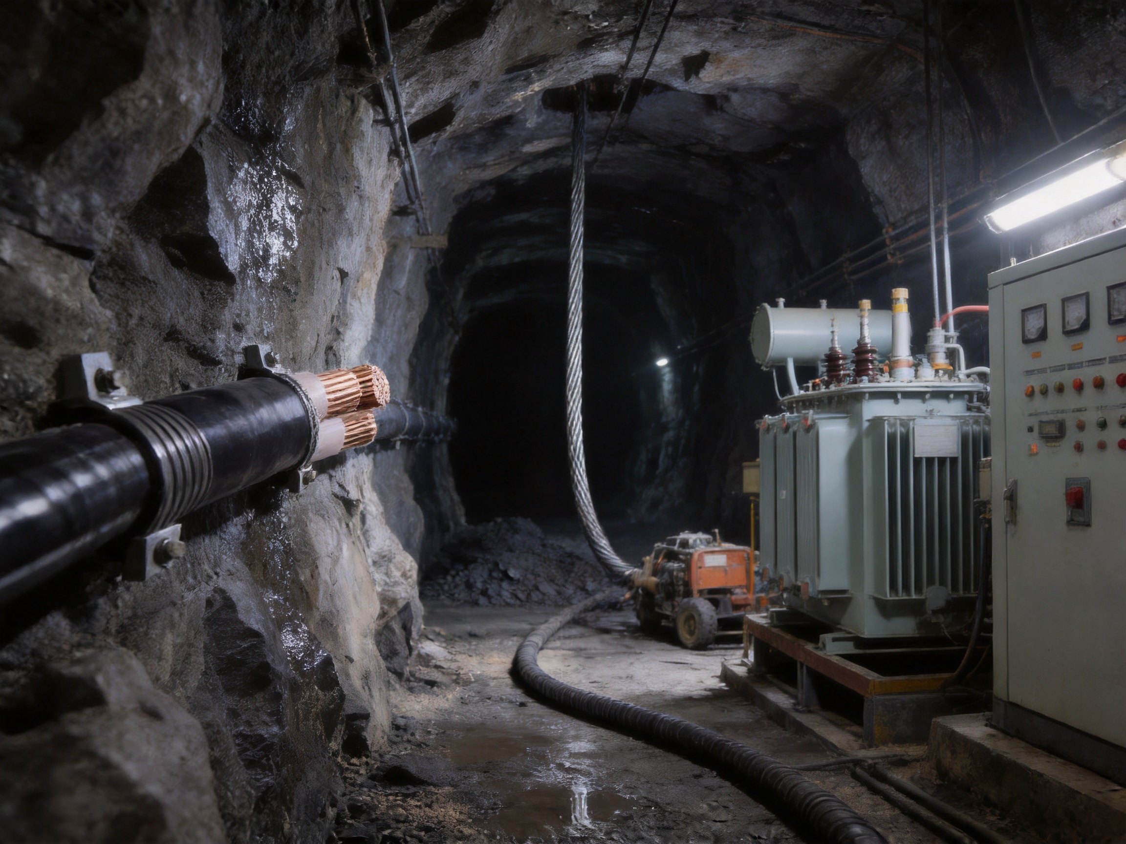
Reliable cable manufacturing begins before production starts. The cable construction must be defined according to voltage rating, conductor cross-section, insulation thickness, shielding arrangement, armor type, sheath material, flame-retardancy requirements, bending radius, and installation category.
Anhui Zhishang Cable Technology Co., Ltd. integrates research and development, production, and sales. Its technical team supports product selection and customized design based on customer drawings, samples, or project requirements. This engineering capability is useful for mining projects because cable systems often need to match specific switchgear, equipment interfaces, routing conditions, or local standards.
Material selection is also controlled according to the intended application. Copper conductor materials must provide stable conductivity and suitable mechanical processing characteristics. XLPE insulation must be compatible with the required voltage class and thermal performance. Semi-conductive compounds must maintain consistent electrical properties. Armor materials must provide the required mechanical protection without creating excessive diameter or weight. Sheath materials must meet flame-retardant and environmental requirements.
During conductor production, copper wires are stranded into a compacted round or sector-shaped conductor. Accurate stranding helps control conductor geometry, flexibility, resistance, and dimensional consistency. Compaction reduces voids and creates a stable surface for shield application.
Process control at this stage can influence later operations. An uneven conductor may lead to variations in shield thickness or insulation eccentricity. Excessive tension can affect the shape and flexibility of the conductor, while insufficient control can create loose wires or dimensional instability. Automated equipment and experienced operators help maintain consistent conductor construction across production batches.
The conductor shield, XLPE insulation, and insulation shield are applied through controlled extrusion processes. For high-voltage cable, the quality of these layers is directly related to electrical reliability. The extrusion line must maintain stable temperature, pressure, material flow, line speed, layer thickness, and concentricity.
Clean processing conditions are especially important. Foreign particles, moisture, surface contamination, or microscopic voids can become potential sites for electrical stress concentration. A well-controlled manufacturing environment reduces the risk of defects within the insulation system.
The insulation thickness is designed in accordance with GB/T 12706.2 requirements based on voltage rating and conductor cross-section. Thickness control must be combined with checks for eccentricity and interface quality. Simply achieving an average thickness is not sufficient if the insulation is uneven around the conductor.
XLPE insulation production generally requires careful thermal processing and, depending on the production system, controlled degassing or conditioning procedures. These steps help reduce volatile by-products and stabilize the insulation after cross-linking. The exact process parameters are determined by the material system, equipment configuration, cable dimensions, and internal quality procedures.
Stable thermal treatment supports the cable's dielectric performance and helps minimize defects that could contribute to partial discharge. It also contributes to consistent insulation resistance and long-term aging behavior.
For MYJV22, double steel tape is applied around the cable core or assembled cable structure with controlled overlap and tension. The tape must remain sufficiently stable to provide mechanical protection while avoiding excessive deformation of the underlying layers.
For MYJV32, fine steel wires are applied with controlled pitch, tension, and alignment. The wire armor must provide the required tensile capability and maintain a uniform structure along the cable length. Production checks may include armor diameter, wire positioning, surface condition, continuity, and resistance to movement during sheath application.
Armoring machinery must be coordinated with cable speed and take-up tension. Excessive tension may compress the insulation system or affect cable flexibility. Insufficient tension may create loose armor, uneven diameter, or poor mechanical stability.
The outer sheath is applied after the insulated and armored structure has been prepared. The sheath extrusion process must produce a smooth, continuous layer with appropriate thickness, adhesion, surface finish, and dimensional consistency. Cooling conditions are controlled to prevent deformation and preserve the cable's roundness.
Flame-retardant PVC or flame-retardant polyolefin may be used according to the required product specification. Where low-smoke and halogen-free performance is required, the selected polyolefin system must be processed within the manufacturer's recommended temperature and speed ranges.
Online diameter monitoring and visual inspection can help identify irregularities during sheath production. Finished cables are then wound on suitable drums or coils to prevent excessive bending and handling damage.
Quality assurance continues after extrusion. The product information identifies full-core, full-length, pure copper specifications, product test reports, and warranty support for standard cable models. Depending on the order and applicable standard, inspection may cover conductor resistance, insulation resistance, sheath integrity, dimensional parameters, high-voltage withstand, partial discharge, flame retardancy, and mechanical performance.
Routine and type testing serve different purposes. Routine tests are generally performed on manufactured lengths to confirm production consistency. Type tests are more extensive and are used to validate a design under specified electrical, thermal, mechanical, and environmental conditions. Customers should confirm which reports and certificates are included with a particular order.
Anhui Zhishang Cable Technology Co., Ltd. operates a production base of approximately 5,000 square meters and has more than 50 employees, including quality engineers and research and development technicians with more than 10 years of industry experience. The company operates 10 automated production lines and reports monthly output of up to 10 million meters.
Production capacity is important for mining projects because large cable orders may involve multiple voltage classes, conductor sizes, armor structures, and delivery stages. A supplier with organized production resources can support both standard replenishment and project-based manufacturing. Capacity alone, however, is not sufficient; it must be supported by process discipline, inspection, technical documentation, and consistent material control.
The company emphasizes full-length and full-core production, pure copper specifications, product test reports, and warranty support for standard cable models. These measures can help customers trace product information and verify that the delivered cable corresponds to the approved construction.
Standard products may be stocked for fast shipment, while customized products generally require a lead time of approximately 7 to 20 days, depending on design complexity, order quantity, material availability, testing requirements, and production scheduling. Customers should confirm delivery terms before placing an order, especially when a mining shutdown or equipment installation has a fixed schedule.
The supplier also supports OEM and ODM development based on customer drawings or samples. This may include modifications to conductor size, sheath material, marking, packaging, shielding, armor, color, voltage class, or other construction details, subject to technical feasibility and applicable standards.
Its stated business philosophy focuses on quality orientation, integrity, and stability. For industrial cable buyers, this approach is relevant because cable performance is closely connected to consistency over time. A cable supplier should be evaluated not only by a single sample but also by its ability to repeat the approved construction across different production batches.
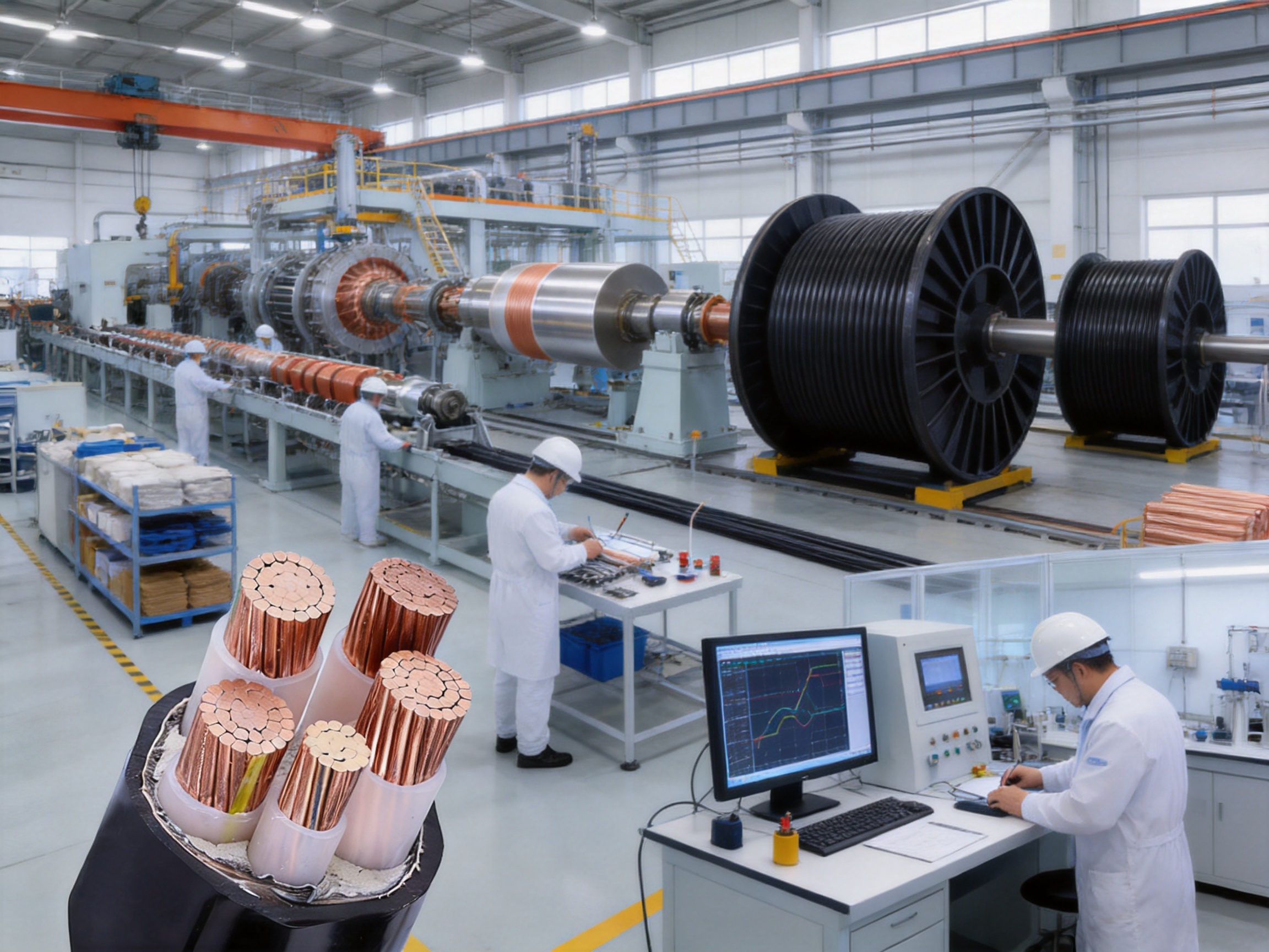
General-purpose high-voltage cables may be designed primarily for utility networks, commercial buildings, industrial plants, or outdoor infrastructure. Mining cables must address additional hazards, including enclosed spaces, flame propagation concerns, falling materials, water exposure, vibration, and difficult maintenance access.
The MYJV family is specifically positioned for underground coal mine high-voltage power supply systems. Its flame-retardant sheath options, armor variants, shielded XLPE insulation, and mobile construction provide a more application-focused solution than a standard fixed cable selected without considering mining conditions.
One advantage of the series is the availability of different constructions for different mechanical risks. A buyer does not need to use a heavily armored cable in every location. MYJV can reduce weight and cost where the cable is protected. MYJV22 can be selected where crushing and impact are the primary concerns. MYJV32 can be used where tensile strength is more important. The mobile construction is intended for equipment movement.
This construction-based selection can improve system efficiency. Over-specifying armor may increase handling difficulty and cost, while under-specifying mechanical protection can create premature failures. Matching the cable design to the installation environment is often more valuable than selecting the heaviest product available.
XLPE provides a strong insulation platform for high-voltage operation, with a stated continuous operating temperature of up to 90°C and short-circuit capability up to 250°C for five seconds. Together with conductor and insulation shields, it supports stable field control and reduced partial-discharge risk.
Compared with older insulation systems that may have lower thermal capability or greater sensitivity to moisture and aging, a properly manufactured XLPE cable can provide a compact, efficient, and reliable solution. The actual performance still depends on correct accessories, installation, testing, and operating conditions.
Flame-retardant PVC and flame-retardant polyolefin sheath options allow the cable to be specified for different fire-safety and environmental requirements. Low-smoke, halogen-free construction may be preferred in enclosed areas where smoke and corrosive gases must be limited.
This gives the buyer more flexibility than a single standard sheath construction. The appropriate material should be chosen according to local mine regulations, equipment compatibility, mechanical requirements, installation location, and customer specifications.
Large or technically complex cable projects may require more than a product code. Cable outer diameter, minimum bending radius, drum size, termination compatibility, installation tension, sheath material, armor arrangement, and marking requirements can affect the complete project.
The supplier's engineering and OEM/ODM capability allows customers to discuss these requirements before production. Technical engineers can provide product selection guidance and tailor cable design solutions according to project needs. This can reduce the risk of ordering a nominally suitable cable that later proves difficult to install or connect.
MYJV22 and MYJV32 are suitable candidates for fixed high-voltage power supply in underground coal mines when their mechanical characteristics match the route. MYJV may be selected in protected areas, while MYJV22 is appropriate for tunnels or routes exposed to crushing and impact. MYJV32 is more suitable for shafts and slopes requiring tensile strength.
Underground substations require dependable connections between incoming high-voltage feeders, transformers, switchgear, and outgoing distribution circuits. Cable selection must consider the substation layout, available space, heat dissipation, bending radius, termination position, fault-current levels, and grounding arrangement.
The cable's black flame-retardant sheath, shielded XLPE insulation, and range of voltage classes support its use in underground distribution systems. The final design should coordinate the cable with switchgear ratings and the substation's fire-protection measures.
MYJV32 is intended for environments where cable tension and height differences are significant. Vertical and inclined installations require detailed mechanical calculations. The cable should be supported using a system that prevents excessive strain at terminations, controls movement, and distributes load along the route.
Installation teams should not pull the cable by the sheath or use armor in a way that creates local stress. Drum handling, pulling tension, sidewall pressure, support spacing, and transition points must be planned before installation.
The mobile construction described as MTJV is intended for high-voltage equipment such as coal shearers and roadheaders. Mobile cable systems must accommodate repeated movement while maintaining electrical shielding and insulation integrity.
Before selection, the user should provide equipment voltage, current, travel distance, movement speed, bending direction, operating frequency, cable support method, and environmental conditions. A mobile cable should be installed with adequate clearance from cutting tools, heated surfaces, hydraulic components, sharp edges, and moving structures.
The available conductor sizes up to 500 mm² and voltage classes up to 18/30 kV enable the series to support long-distance underground transmission when the cable is correctly sized. Long routes require careful evaluation of voltage drop, charging current, thermal capacity, short-circuit withstand, installation grouping, and system protection coordination.
For long cable runs, the engineering team should also consider joint spacing, drum length, transport access, pulling arrangements, and testing after installation. A cable's nominal voltage and conductor area are only the starting points for a complete transmission design.
Cable performance depends heavily on installation quality. Before delivery, drums should be inspected for damage, correct labeling, sealed ends, and signs of moisture entry. Cable ends should remain sealed until termination work begins. Drums should be stored upright on stable ground and protected from impact, flooding, and excessive heat.
During unwinding, the drum should rotate in the direction indicated by the manufacturer's instructions. The cable should be pulled smoothly without sudden jerks. Pulling tension should remain within the approved limit, and rollers should be positioned to prevent the cable from scraping against the ground or tunnel structure.
The minimum bending radius must be respected at every stage, including drum removal, temporary storage, routing around corners, connection to equipment, and final termination. Fixed installations should maintain at least 15 times the cable outer diameter, while mobile installations should maintain at least 20 times the cable outer diameter according to the supplied specifications.
Armor, metallic screens, and shields must be connected according to the system's earthing and bonding design. Incorrect grounding can affect touch voltage, electromagnetic behavior, fault-current paths, and protection operation. Terminations should use accessories compatible with the cable's voltage class, insulation diameter, shield design, and conductor size.
After installation, visual inspection should verify sheath condition, support spacing, bend-radius compliance, identification, and clearance from moving equipment. Electrical testing should be performed by qualified personnel using procedures appropriate to the cable type and governing standard. Test results should be recorded as part of the mine's maintenance and asset-management documentation.
Routine inspection can identify problems before they develop into electrical failures. Maintenance teams should check for sheath cuts, abrasion, flattening, exposed armor, water accumulation, loose supports, excessive sag, signs of overheating, and damage at terminations or joints.
Thermal monitoring may be useful in heavily loaded areas. Unusual temperature rise can indicate overload, poor connection, unbalanced current, restricted heat dissipation, or damaged insulation. Cable loading should remain within the calculated ampacity for the actual installation conditions.
Mobile cables require more frequent inspection because their operating environment includes repeated bending and mechanical contact. The movement path should be examined for dragging, twisting, crushing, and interference with machinery. Any cable showing exposed conductors, severe sheath damage, or evidence of internal mechanical failure should be removed from service according to mine safety procedures.
Water ingress should be treated seriously. Even when the sheath is designed for humid conditions, damage to the outer layer or poorly sealed ends can allow moisture to migrate into the cable. Termination areas should be kept clean and dry during installation, and damaged sheath sections should be assessed by qualified technicians.
A documented maintenance program can extend service life and improve safety. Records should include cable identification, installation date, route, voltage, conductor size, model, test results, inspection findings, repairs, and replacement history. This information helps engineers identify recurring problems and improve future cable selection.
| Parameter | Specification |
|---|---|
| Conductor | Copper conductor, compacted round or sector-shaped |
| Cross-section range | 25 mm² to 500 mm² |
| Rated voltage | 3.6/6 kV, 6/10 kV, 8.7/15 kV, 12/20 kV, 18/30 kV |
| Insulation material | Cross-linked polyethylene |
| Shielding structure | Conductor semi-conductive shield and insulation semi-conductive shield |
| MYJV22 armor | Double steel tape armor |
| MYJV32 armor | Fine steel wire armor |
| MYJV construction | Non-armored fixed-installation structure |
| Mobile construction | Flexible conductor and mobile metal-shielded structure |
| Sheath material | Flame-retardant PVC or flame-retardant polyolefin, including LSZH options |
| Power-frequency test | 3.5U0 for five minutes, subject to the applicable test procedure |
| Partial discharge | Not more than 10 pC at 1.73U0 |
| Insulation resistance | At least 1000 MΩ·km at 20°C |
| Long-term operating temperature | -40°C to +90°C |
| Short-circuit temperature | Up to 250°C for five seconds |
| Minimum bending radius | 15 times outer diameter for fixed installation; 20 times outer diameter for mobile installation |
| Flame-retardancy references | MT 818.12 and GB/T 19666 bundle flame test, according to the stated product configuration |
| Sheath color | Black |
Technical values may vary according to voltage class, conductor cross-section, final construction, sheath material, customer specification, and the applicable edition of the governing standard. Buyers should request the exact technical data sheet and test documentation for the selected model before approval.
The first selection question is whether the installation is fixed or mobile. Fixed routes can generally use MYJV, MYJV22, or MYJV32 depending on mechanical hazards. Mobile equipment requires a construction designed for repeated movement and bending.
The second question concerns mechanical exposure. If the cable is installed in a protected route, a non-armored cable may be sufficient. If crushing, impact, rodents, or external contact are significant risks, MYJV22 may be preferred. If the route is vertical, inclined, suspended, or subject to substantial tensile loads, MYJV32 should be evaluated.
The third question is electrical. The system voltage, load current, fault level, voltage drop, cable length, installation grouping, and ambient temperature must be established. The conductor cross-section should be calculated rather than selected only by matching the equipment nameplate.
The fourth question concerns the environment. The designer should evaluate water, humidity, chemical exposure, temperature, smoke requirements, ventilation, tunnel width, access restrictions, and the possibility of future route changes. These factors influence sheath selection, armor selection, cable diameter, and installation accessories.
The fifth question concerns compliance and documentation. The buyer should confirm the required standards, inspection plan, type-test evidence, routine-test reports, flame-retardancy documentation, packing method, marking, warranty conditions, and delivery schedule.
Finally, the cable should be reviewed as part of the complete system. Terminations, joints, supports, switchgear, protective relays, grounding, cable cleats, trays, and equipment interfaces must be compatible. A high-quality cable cannot compensate for unsuitable accessories or poor installation practices.
An integrated manufacturer can coordinate technical design, materials, production, testing, packaging, and customer service through one organization. This can simplify communication and reduce the risk of discrepancies between a design drawing, production order, test report, and delivered product.
For mining customers, technical communication is especially important. A cable order may include multiple voltage levels, conductor areas, armor types, drum lengths, and sheath requirements. An experienced supplier can review the application and identify potential issues before production, such as insufficient tensile strength, excessive outer diameter, unsuitable flexibility, or incompatible termination dimensions.
Anhui Zhishang Cable Technology Co., Ltd. provides cable products for industrial automation, weak-current engineering, intelligent manufacturing, appliance equipment, power engineering, and related fields. Its experience across multiple cable applications supports a broader understanding of conductor, insulation, shielding, sheath, and customization requirements.
The company serves domestic and international markets, including customers in North America, Australia, Japan, and parts of Eurasia. International project experience can be helpful when customers require documentation, packaging, labeling, communication, and technical coordination for cross-border delivery.
Its production capacity, automated equipment, engineering team, quality personnel, and customization support make it suitable for both standard cable procurement and project-specific development. Customers should nevertheless evaluate each product against the exact technical requirements of their mine, country, equipment manufacturer, and safety authority.
MYJV is a non-armored cable intended for fixed installation in protected locations. MYJV22 uses double steel tape armor and provides greater resistance to crushing and impact. MYJV22 is generally more suitable for tunnels, direct-buried sections, and other routes exposed to external mechanical damage.
MYJV32 should be considered when tensile strength is a major requirement, such as in vertical shafts, inclined roadways, suspended routes, or installations with significant elevation differences. MYJV22 is primarily intended to improve crush and impact resistance, while MYJV32 is designed to provide higher tensile strength through fine steel wire armor.
MYJV is intended for fixed installation and should not normally be used for equipment that moves frequently. Mobile applications require a flexible construction, identified in the supplied information as MTJV, with flexible conductors and a mobile metal-shielded structure.
The cable uses cross-linked polyethylene, commonly known as XLPE, as the main insulation. XLPE provides high dielectric performance, thermal stability, mechanical strength, and resistance to moisture when correctly manufactured and installed.
The stated voltage ratings are 3.6/6 kV, 6/10 kV, 8.7/15 kV, 12/20 kV, and 18/30 kV. The appropriate rating must be selected according to the mining power system and the applicable electrical design requirements.
The stated conductor cross-section range is 25 mm² to 500 mm². The correct size depends on load current, voltage drop, installation conditions, short-circuit requirements, and the overall system design.
The product information states that the cable uses flame-retardant sheath materials and passes MT 818.12 and GB/T 19666 bundle flame testing. The exact performance should be confirmed for the selected construction and sheath material.
The stated sheath options include flame-retardant polyolefin with low-smoke, halogen-free characteristics. Customers should specify LSZH requirements when requesting a quotation and confirm the relevant test documentation.
The stated minimum bending radius is 15 times the cable outer diameter for fixed installation and 20 times the cable outer diameter for mobile installation. The mobile value is larger because repeated movement places additional stress on the cable.
The stated long-term operating range is -40°C to +90°C. Under short-circuit conditions, the conductor temperature may reach up to 250°C for five seconds, subject to the specified design and installation conditions.
The cable uses a conductor semi-conductive shield, XLPE insulation, and an insulation semi-conductive shield. These layers help smooth the electric field and reduce localized electrical stress. The stated partial-discharge value is no more than 10 pC at 1.73U0.
The company supports OEM and ODM development based on customer drawings or samples. Customization may involve construction, sheath material, conductor size, marking, packaging, or other technical features, subject to engineering review and production feasibility.
Customers should provide the required model, rated voltage, conductor material, conductor cross-section, number of cores, installation type, armor requirement, cable length, sheath material, operating environment, applicable standards, delivery destination, and required documentation. For mobile cable, movement distance and bending conditions should also be supplied.
Depending on the project, customers may request routine-test reports, type-test evidence, insulation resistance results, high-voltage withstand results, partial-discharge results, dimensional records, flame-retardancy reports, conductor resistance data, and a product certificate. The documentation package should be agreed before production.
The supplied company information indicates that standard products may be stocked for fast shipment, while customized products generally require approximately 7 to 20 days. Actual delivery depends on quantity, construction, materials, testing, production capacity, and shipping arrangements.
The MYJV, MYJV22, and MYJV32 mining high-voltage cable family provides a structured approach to underground power distribution. Its copper conductor, XLPE insulation, semi-conductive shielding, flame-retardant sheath, and model-specific armor configurations are designed to address the electrical and mechanical challenges of mining environments.
MYJV offers a lightweight and economical choice for protected fixed installation. MYJV22 provides enhanced crush and impact resistance for demanding fixed routes. MYJV32 offers greater tensile strength for shafts, slopes, and installations involving significant height differences. The related mobile construction provides a solution for high-voltage mining equipment that must move repeatedly.
Compared with general-purpose high-voltage cables, the series offers advantages through mining-specific construction options, flame-retardant materials, controlled electric-field design, partial-discharge performance, moisture resistance, and application-oriented engineering. These advantages are supported by the manufacturer's production base, automated production lines, technical personnel, quality engineers, testing procedures, OEM/ODM capability, and project support.
Successful cable selection still requires a complete engineering assessment. Voltage, current, conductor size, mechanical loads, bending radius, fire requirements, moisture, grounding, accessories, installation method, and maintenance conditions must all be evaluated. When the cable model is correctly matched to the mine environment and installed according to approved procedures, the product family can provide a dependable foundation for underground high-voltage power supply, distribution, and transmission.
GB/T 12706.2, Power Cables with Extruded Insulation and Their Accessories for Rated Voltages from 1 kV to 35 kV.
GB/T 19666, General Rules for Flame Retardant and Fire Resistant Wires and Cables.
MT 818.12, Technical Requirements and Test Methods for Mining Cables.
International Electrotechnical Commission, Power Cable Design, Testing, Installation, and Maintenance Principles.
Manufacturer-provided technical information for MYJV, MYJV22, MYJV32, and related mobile mining high-voltage cable constructions.
Manufacturer-provided product and company information concerning XLPE insulation, shielding, armor, sheath materials, production capacity, quality assurance, and customization services.

We firmly believe that good cables are not only a competition of materials, but also a reflection of craftsmanship, quality, and responsibility.

Links
Product
Send Inquiry
No. 29 Sankeshu Road, Xuanzhou District, Xuancheng City, Anhui Province, China
+86-18621104555/+86-563-2622999
 Electrical Cable Manufacturer
OEM/ODM Wire and Cable Solutions
Electrical Cable Manufacturer
OEM/ODM Wire and Cable Solutions
 English
 Español
 عربى
عربى
 русский