
Get more content that can help you
Content
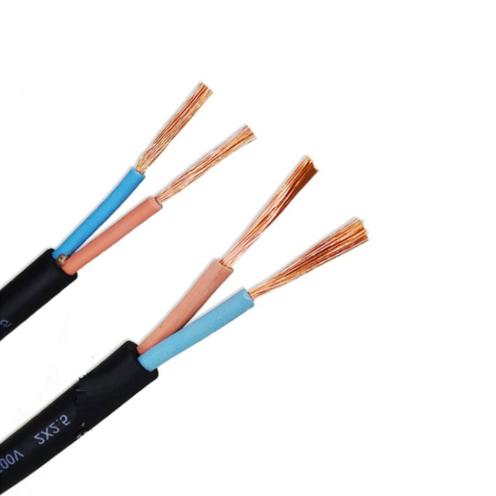
Industrial automation depends on cables that can do much more than carry electrical power. In a modern robot cell, one cable assembly may need to transmit motor power, encoder feedback, control signals, bus communication, and safety circuits while moving continuously through a cable carrier or robot joint. It must resist bending, twisting, abrasion, oil, coolant, vibration, and electromagnetic interference. If the cable fails or signal quality deteriorates, the result may be inaccurate positioning, communication errors, unplanned downtime, or damage to expensive automation equipment.
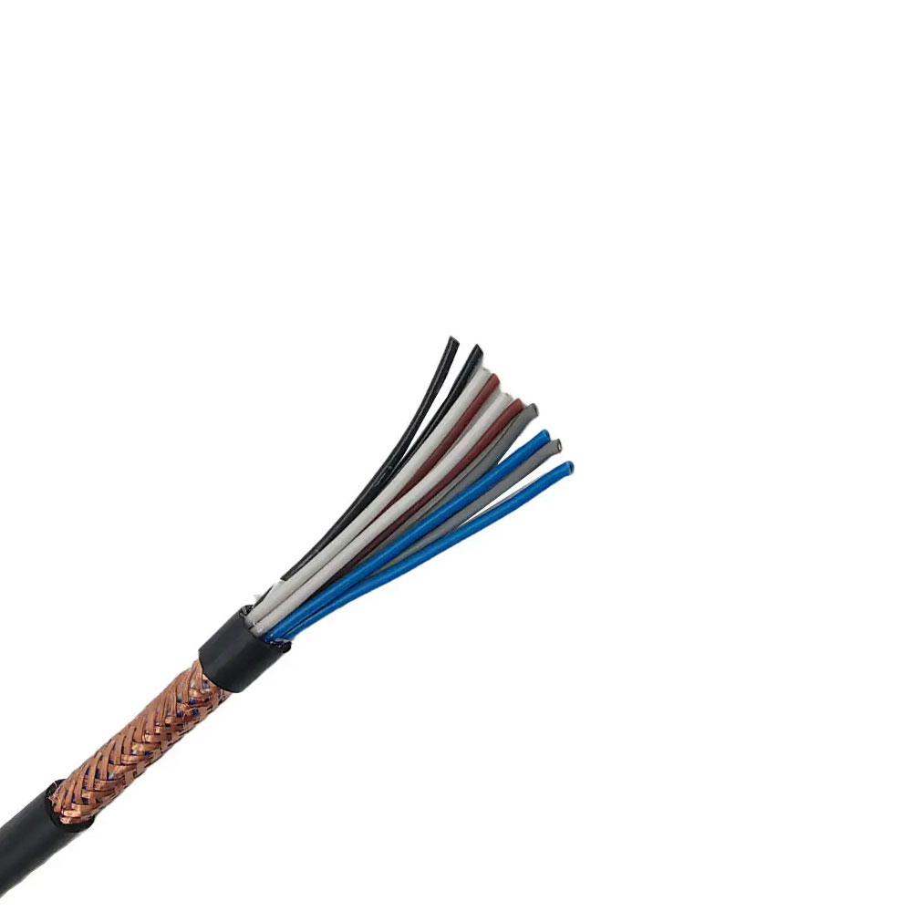
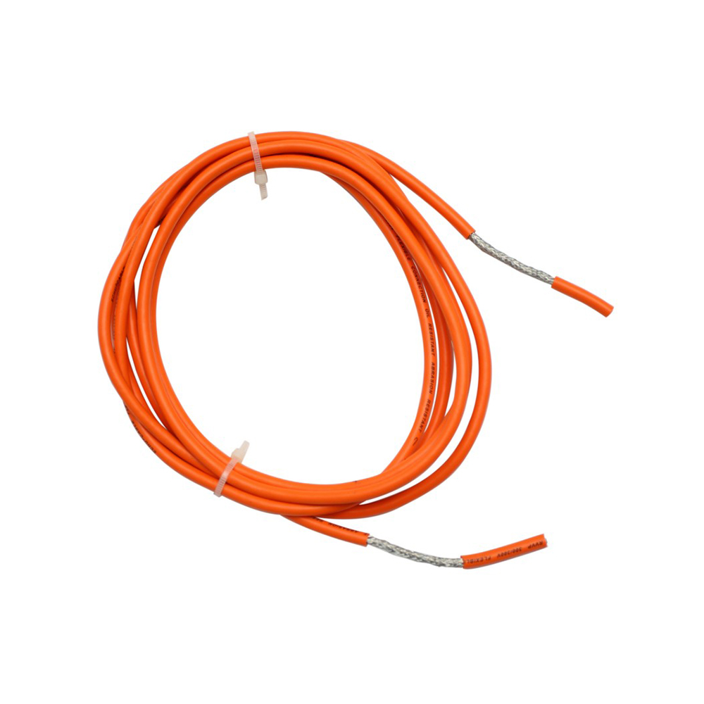
The JQR-246P PVC Robot Cable is designed for this demanding combination of electrical and mechanical requirements. Its central design feature is a full tinned-copper braided shield that surrounds the cable core and helps maintain electromagnetic protection during repeated movement. Fine-stranded oxygen-free copper conductors, flexible PVC or elastomer insulation, carefully arranged cable cores, and a modified PVC outer sheath work together to create a practical solution for industrial robots and other dynamic automation systems.
This article examines the cable’s construction, performance advantages, manufacturing strengths, application value, and selection considerations. It also explains why a properly designed full-copper shield can offer an advantage over basic unshielded robot cables or lower-cost shielded products that are not optimized for continuous movement.
Industrial robots operate through coordinated movement. Six-axis robots rotate, extend, retract, and change direction thousands of times during a working shift. SCARA robots perform rapid horizontal movements and vertical strokes. Automated guided systems, machining centers, packaging equipment, welding cells, and material-handling machines can all expose cables to continuous flexing and vibration.
In these environments, cable performance is determined by several factors at the same time. A cable may have excellent electrical conductivity but fail mechanically after repeated bending. Another cable may be flexible but provide inadequate shielding for servo or encoder signals. A product with a durable jacket may still suffer from internal conductor fatigue if its core structure is not designed for movement.
Robot cables therefore require a balanced construction. The conductor must withstand repeated flexing. The insulation must remain flexible without cracking. The cable core must be arranged to control internal friction. The shield must maintain electrical continuity as the cable moves. The outer sheath must protect the internal structure from abrasion, oil, moisture, and industrial contaminants.
The JQR-246P approach addresses these requirements through a layered design. Power, signal, control, feedback, and communication conductors can be integrated into one cable assembly. Critical signal pairs may receive additional individual shielding, while a high-density tinned copper braid provides overall shielding. This arrangement helps reduce crosstalk and creates a more stable transmission path for sensitive control information.
The JQR-246P is a flexible PVC robot cable with full copper shielding. It is intended for general industrial automation applications where the cable must move repeatedly and where moderate to high electromagnetic interference may be present.
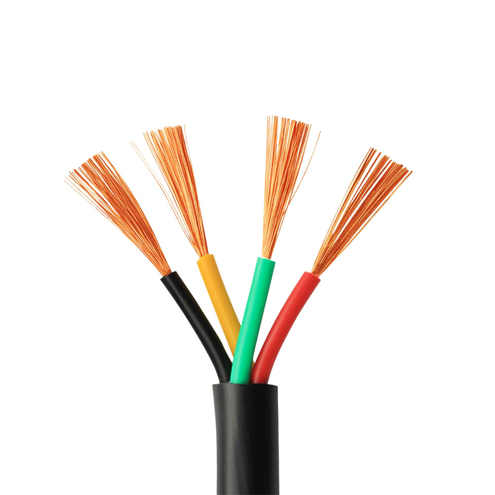
The cable can be configured with multiple cores, including common arrangements such as 4, 8, 12, or 19 cores. Depending on the customer’s design requirements, the cable may combine power conductors, control lines, signal lines, twisted pairs, encoder feedback pairs, and bus communication circuits.
Conductor cross-sectional areas commonly range from 0.25 square millimeters to 16 square millimeters. The exact conductor size, core count, voltage rating, sheath color, shielding arrangement, and cable diameter can be adjusted according to the application. Standard configurations may be used for faster delivery, while customized versions can be developed from drawings, samples, or defined electrical and mechanical specifications.
The principal performance features include fine-stranded oxygen-free copper conductors, flexible insulation, controlled core stranding, a tinned copper braided shield, and a modified PVC outer sheath. The cable is intended for mobile installation in cable carriers and other controlled-motion environments, with performance depending on the selected construction, installation method, travel length, speed, acceleration, torsion, and environmental conditions.
| Item | Typical Product Characteristic | Application Significance |
|---|---|---|
| Product type | Flexible PVC robot cable | Designed for dynamic industrial automation |
| Conductor | Fine-stranded oxygen-free copper, Class 5 or Class 6 | Improves flexibility and electrical conductivity |
| Conductor range | Approximately 0.25 to 16 square millimeters | Supports signal, control, and power circuits |
| Core arrangement | Multi-core, including power, control, signal, feedback, and bus circuits | Enables integrated cable design |
| Overall shield | High-density tinned copper braid, commonly at least 80 percent coverage and up to 85 percent or more according to configuration | Reduces electromagnetic interference and signal radiation |
| Additional shielding | Individual foil shielding may be applied to critical pairs | Controls crosstalk in sensitive circuits |
| Outer sheath | Modified flexible PVC | Provides abrasion, oil, moisture, and general industrial protection |
| Voltage options | Commonly 300/500 V or 0.6/1 kV | Supports different automation power requirements |
| Flame behavior | Designed to comply with IEC 60332-1-2 requirements where specified | Improves installation safety |
| Dynamic bending | Configuration-dependent; commonly specified from 5 times the outer diameter in selected designs, or 7.5 to 10 times the diameter for mobile carrier installation | Requires correct installation and model selection |
| Operating temperature | Typical mobile range of approximately -5°C to +70°C; fixed range may extend to approximately -15°C to +70°C | Suitable for many general industrial environments |
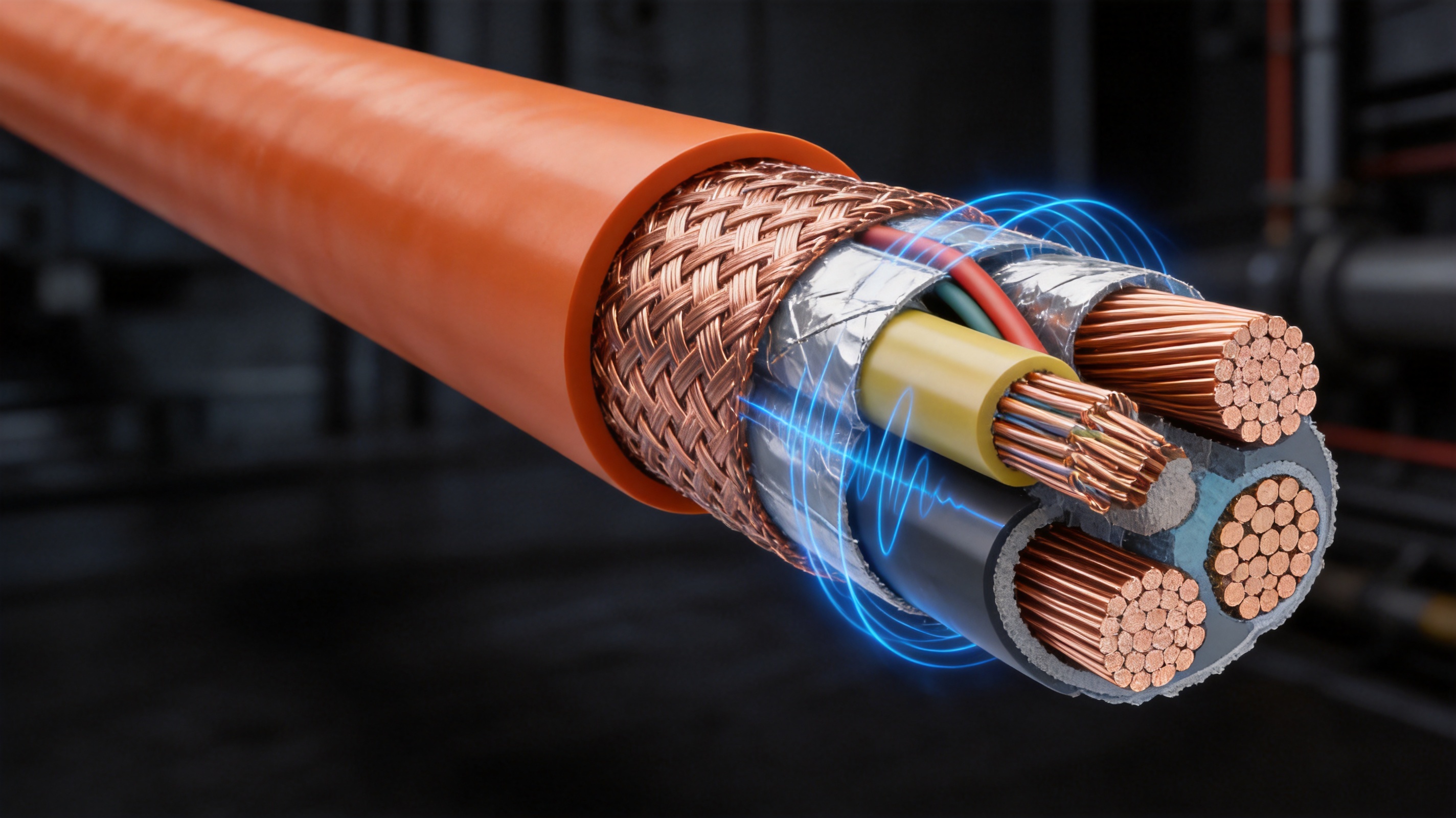
The most important differentiating feature of this robot cable is the full copper braided shielding layer. Shielding is essential when a cable is installed near variable-frequency drives, servo motors, switching power supplies, contactors, welding equipment, or high-current conductors. These sources can generate electromagnetic fields that interfere with low-level feedback signals and communication circuits.
A full copper braid creates a conductive barrier around the cable core. When correctly grounded, it helps divert unwanted electrical noise away from sensitive conductors. It can also reduce the radiation of internally generated noise from power conductors into nearby equipment and signal cables.
Not all shields perform equally during dynamic movement. A shield that is poorly braided, loosely applied, or mechanically incompatible with repeated bending may develop gaps, broken strands, or unstable electrical continuity. Even if the cable appears intact from the outside, shield resistance and coverage can change as the cable is flexed. This can reduce interference protection in the exact operating conditions where shielding is most important.
The JQR-246P design uses high-density tinned copper wires in a braided structure. Tinned copper provides good electrical conductivity while improving resistance to oxidation compared with bare copper in certain industrial environments. The braid is engineered to preserve coverage and structural continuity during repeated cable movement. This is particularly important for robotic applications where the cable may bend in multiple directions over a long operating cycle.
The stated overall shielding coverage is commonly at least 80 percent, with selected product configurations designed for 85 percent or higher coverage. Actual shielding effectiveness depends on braid density, grounding quality, frequency, cable geometry, installation, connector design, and the use of any individual pair shields. For this reason, the cable should be evaluated as part of the complete system rather than as an isolated component.
External electromagnetic interference can enter a cable through capacitive or inductive coupling. A shield helps reduce this coupling by creating a conductive layer between the interference source and the internal conductors. In a robot cell, this may help protect encoder feedback, industrial bus communication, sensor signals, and low-voltage control circuits from noise produced by motors and drives.
The benefit is especially important when power and signal conductors share one cable assembly. Without adequate separation or shielding, voltage transitions from servo drives may create disturbances in feedback pairs. These disturbances can appear as communication retries, unstable readings, false sensor signals, positioning errors, or intermittent machine alarms.
Power conductors can generate electromagnetic fields that affect nearby signal conductors. A carefully arranged multi-core design helps reduce this effect by controlling conductor placement, twisting certain pairs, and using shielding around the complete assembly. Critical communication or encoder pairs may also receive independent aluminum foil shielding before the overall copper braid is applied.
This layered approach is valuable because different types of interference require different control methods. Pair twisting reduces the area exposed to external fields and helps cancel induced noise. Individual foil shielding provides a local barrier around particularly sensitive circuits. The overall copper braid offers broad protection for the entire cable and improves grounding continuity.
For a fixed cable, shielding performance can often be evaluated under static conditions. A robot cable must maintain acceptable performance while moving. The braid must bend with the rest of the cable without concentrating stress in a small area. A suitable braiding process, correct tension control, and compatible jacket extrusion are therefore essential.
The JQR-246P design emphasizes dynamic anti-interference capability. The objective is not only to provide high shielding coverage when the cable is new, but also to retain useful electrical continuity during repeated movement. This gives the cable an advantage over basic products that use a simple foil layer without adequate mechanical reinforcement or that rely on a low-coverage shield not intended for continuous motion.
JQR-246P PVC Robot Cable, Full Copper Shielding
Electrical shielding alone does not make a suitable robot cable. The cable must also tolerate the mechanical forces created by continuous movement. These forces include bending, tensile stress, compression in cable carriers, torsion, friction between cores, and rubbing against guides or adjacent components.
The JQR-246P uses fine-stranded conductors rather than solid conductors. Fine stranding allows the conductor to flex repeatedly with less stress concentration in any single copper element. The conductors are specially stranded and arranged to support dynamic use. Oxygen-free copper contributes good conductivity and can help reduce resistance losses in power and control circuits.
The conductor class, strand diameter, lay length, and stranding sequence all influence cable life. A cable with very fine strands may be flexible, but the strands must still be controlled during processing so that they do not shift excessively under movement. The insulation must also fit the conductor correctly. Too much looseness can increase internal movement, while excessive compression can reduce flexibility.
Inside a multi-core robot cable, each conductor moves slightly as the cable bends. If the cores are poorly arranged, they can rub against each other, migrate toward the outside of the bend, or create localized pressure points. Over time, this may damage insulation or cause conductor fatigue.
The JQR-246P uses an optimized core stranding pitch and flexible filler or inner sheath structure to stabilize the cable assembly. The purpose is to keep the conductors positioned, reduce internal friction, and distribute bending forces more evenly across the cable. This is a key difference between a cable designed for fixed installation and one designed for continuous movement.
Twisted pairs may be used for control, encoder, and communication circuits. Pair twisting helps maintain signal balance and reduces susceptibility to crosstalk. The twist rate must be selected carefully because an excessively tight twist can increase mechanical stiffness, while an insufficient twist may not provide the desired electrical performance.
The outer sheath is the first line of defense against the industrial environment. It must resist abrasion caused by cable carriers, guide channels, robot arms, and adjacent components. It must also retain flexibility when exposed to oil, grease, coolant, humidity, and repeated temperature changes.
The modified PVC sheath used for this cable is intended to provide practical protection for general industrial environments. It offers a balance between flexibility, abrasion resistance, oil resistance, manufacturing cost, and ease of processing. The sheath may be supplied in black or gray, with other colors possible for identification or project requirements.
PVC is not suitable for every extreme environment. Applications involving very high temperatures, severe chemical exposure, prolonged outdoor weathering, aggressive solvents, or exceptional torsional loads may require a polyurethane, thermoplastic elastomer, fluoropolymer, or other specialized jacket. However, for many automation projects, PVC provides a cost-effective combination of protection and dynamic performance.
The minimum bending radius is an important design parameter. Product information for this family includes a minimum radius of 5 times the outer diameter in selected highly flexible designs, while mobile cable-carrier installation is commonly specified at 7.5 to 10 times the cable diameter depending on the exact construction. These values should not be treated as interchangeable.
The correct radius depends on the cable configuration, core arrangement, shield construction, movement profile, carrier design, travel speed, acceleration, and torsion. A smaller radius may be available for a specific model after testing, but the installation should always follow the manufacturer’s approved specification for that exact cable size and structure.
Exceeding the recommended bending radius can increase stress on the conductors, shield, insulation, and sheath. It may also cause the cable to buckle inside a carrier. In practical installations, the cable should be supported without forced twisting, and the carrier should be selected to provide sufficient internal width and height without compressing the cable.
Modern robots often require one cable assembly to carry multiple electrical functions. Motor power may operate at high current and produce fast switching transients, while encoder feedback and bus communication may use low-voltage differential signals. Combining these circuits creates space and installation advantages, but it also creates a need for careful cable design.
The JQR-246P is intended to support integrated transmission of power, control, signal, feedback, and bus circuits. The internal structure can use dedicated conductors, twisted pairs, pair shielding, fillers, and an overall copper braid. This layered arrangement helps separate the electrical functions within one flexible assembly.
Signal integrity is not simply a matter of conductor resistance. It also depends on impedance consistency, capacitance, inductance, pair balance, shielding, grounding, connector quality, and the overall routing path. For encoder or communication circuits, a stable cable geometry can help reduce reflections and waveform distortion. For analog sensors, effective shielding can reduce noise that would otherwise appear as measurement variation.
The cable can therefore help reduce the risk of error rates caused by electromagnetic coupling. It cannot eliminate all system-level interference, because grounding, drive filtering, connector termination, cabinet layout, and machine wiring also affect performance. Nevertheless, a well-constructed shielded cable provides a strong foundation for reliable communication.
Servo systems depend on accurate feedback. Encoders report position, speed, and sometimes motor commutation information to the controller. If feedback signals are disturbed, the control system may respond incorrectly or generate a fault.
Dedicated twisted pairs with optional individual shielding are suitable for many encoder applications. The overall copper braid adds another protective layer when the cable is routed near servo power conductors. Correct termination of the shield at the equipment interface is essential. Depending on the system design, shield bonding may be required at one or both ends, and the grounding method should follow the drive and controller manufacturer’s instructions.
Industrial communication buses may be sensitive to cable impedance, pair geometry, and external noise. A cable designed with controlled twisted pairs and appropriate shielding can help preserve communication stability over repeated movement. Applications may include robot controller links, feedback networks, sensor communication, and other industrial data circuits.
When selecting a configuration, the user should confirm the requirements of the specific bus protocol, including conductor size, characteristic impedance, capacitance, pair arrangement, termination, and maximum permitted length. The JQR-246P can be configured for different control and communication needs, but the final design should be validated against the electrical requirements of the selected system.
Dynamic service life is influenced by more than a single bending-cycle number. The actual life of a robot cable depends on bending radius, travel distance, movement speed, acceleration, torsion, temperature, carrier alignment, installation tension, and exposure to chemicals or abrasive materials.
Product information for this type of cable refers to millions of reciprocating movements, with stated performance depending on the configuration and test method. Some product descriptions identify a target of more than 2 million to 5 million carrier movements, while selected application claims refer to testing of up to 10 million bending cycles. These figures should be understood as configuration-specific test results rather than a universal life guarantee for every installation.
The practical advantage is that the cable is engineered for long-cycle dynamic service rather than occasional movement. It is intended for applications such as material handling, automotive assembly, electronic equipment, machine tools, packaging, and general robotic automation. When the cable is correctly matched to the movement profile, it can reduce replacement frequency and help lower maintenance costs.
Robot arms can impose torsional movement in addition to bending. A cable routed through a rotating joint may twist along its length, especially when the cable is not guided in a controlled manner. The product information indicates that certain constructions can withstand continuous torsion of approximately plus or minus 180 degrees per meter.
Torsion capability depends heavily on the cable’s internal construction and the installation method. A cable designed for a linear carrier should not automatically be used in a high-torsion robot dress pack. If a robot joint produces continuous multi-axis rotation, the customer should confirm that the selected cable is approved for the specific torsion angle, speed, cycle count, and routing arrangement.
In a cable carrier, the outer sheath may experience continuous contact with the carrier surface. In a robot dress pack, the cable may rub against protective sleeves, clamps, or neighboring cables. A tear-resistant and abrasion-resistant PVC compound helps protect the cable from premature external damage.
Good installation practice remains important. The cable should not be clamped so tightly that the sheath is compressed. Fixed points should be positioned outside the active bending zone where possible. The cable should be allowed to move naturally within the carrier, and sharp edges should be removed from brackets and guides.
Automation equipment is often exposed to oil, grease, coolant, weak acids, weak alkalis, moisture, dust, and changing temperatures. The PVC outer sheath of the JQR-246P is designed to provide basic environmental protection for these general industrial conditions.
Oil resistance is especially useful in automotive manufacturing, machining, assembly, and maintenance environments. The sheath is described as resistant to oil and compatible with test requirements associated with IEC 60811-2-1 where specified. Actual resistance depends on the type of oil, concentration, temperature, duration of exposure, and mechanical stress applied during exposure.
The cable is also intended to tolerate humidity and ordinary industrial moisture. However, the cable assembly should not be considered automatically waterproof. If the application requires immersion, outdoor direct burial, high-pressure washing, or a defined ingress-protection rating, the complete cable system must be designed and tested for that condition.
The typical mobile operating temperature is approximately -5°C to +70°C, while fixed installation may allow a lower minimum temperature of approximately -15°C, depending on the selected model. The user should confirm the exact temperature range before installation, particularly in cold storage facilities, outdoor equipment, heat-intensive machine areas, or applications near welding operations.
The JQR-246P is positioned as an economical robot cable rather than an extreme-environment premium cable. Its value comes from combining useful dynamic performance and comprehensive copper shielding with a PVC construction that is generally more cost-effective than specialized polyurethane or fluoropolymer products.
An unshielded flexible cable may be adequate for simple power transmission in a low-noise environment. It is less suitable when power and signal conductors are routed together near servo drives or motors. Without an overall shield, the cable offers less protection against external interference and may radiate more internally generated noise.
The full copper braid in the JQR-246P provides a more complete electromagnetic barrier. This can reduce the risk of encoder errors, bus communication interruptions, and unstable sensor signals. The improvement is particularly valuable when the cable path is crowded or when the machine layout leaves limited space for separating power and signal wiring.
Aluminum foil can provide effective high-frequency shielding, but foil-only constructions may require a drain wire and may not provide the same mechanical flexibility as a properly designed copper braid. Repeated bending can stress the foil, adhesive, or drain-wire connection.
A copper braid provides both electrical conductivity and mechanical flexibility. It can be used as an overall shield and may be combined with individual foil shields around sensitive pairs. This hybrid structure helps address both broad electromagnetic exposure and local high-frequency crosstalk.
Standard fixed-installation cable is not designed for continuous flexing. Its conductor stranding, insulation, filler, shield, and jacket may all be optimized for stationary service rather than repeated movement. Using it in a robot carrier can result in conductor breakage, insulation cracking, or shield failure.
The JQR-246P is built around dynamic requirements. Fine-stranded conductors, flexible materials, controlled core geometry, and a movement-compatible outer sheath make it more appropriate for recurring automation motion.
Some automation applications require high-performance polyurethane, thermoplastic elastomer, or fluoropolymer cables for severe abrasion, outdoor use, extreme temperature, chemical exposure, or very high torsion. These products can offer specialized advantages but may also increase project cost.
For general industrial automation, a PVC robot cable can provide a practical balance of flexibility, shielding, environmental protection, and affordability. It is especially attractive for small and medium-sized automation projects where the operating conditions are demanding but do not require the highest level of specialty polymer performance.
Product performance depends on manufacturing consistency. A carefully designed cable can lose its intended advantages if conductor stranding, insulation extrusion, core assembly, shielding, or sheath application is not controlled accurately.
The manufacturer behind this product integrates research and development, production, and sales. Its production base covers approximately 5,000 square meters and includes more than 10 automated production lines. The company reports a monthly production capacity of up to 10 million meters, providing the scale needed for both standard cable supply and customized projects.
The process begins with suitable copper conductors selected for electrical and mechanical performance. Fine copper wires are drawn or prepared to the required diameter and then stranded into flexible conductor groups. Stranding parameters must be controlled to achieve consistent resistance, flexibility, and mechanical stability.
For power cores, conductor size and resistance are selected according to current capacity, voltage drop, temperature rise, and installation conditions. For signal and communication pairs, conductor diameter, pair balance, capacitance, and twist geometry are important. Class 5 or Class 6 constructions can be used where higher flexibility is required.
Each conductor receives a flexible PVC or elastomer insulation layer. Extrusion equipment must maintain stable wall thickness, concentricity, surface finish, and color identification. Inconsistent insulation can affect electrical performance and may create mechanical weak points during bending.
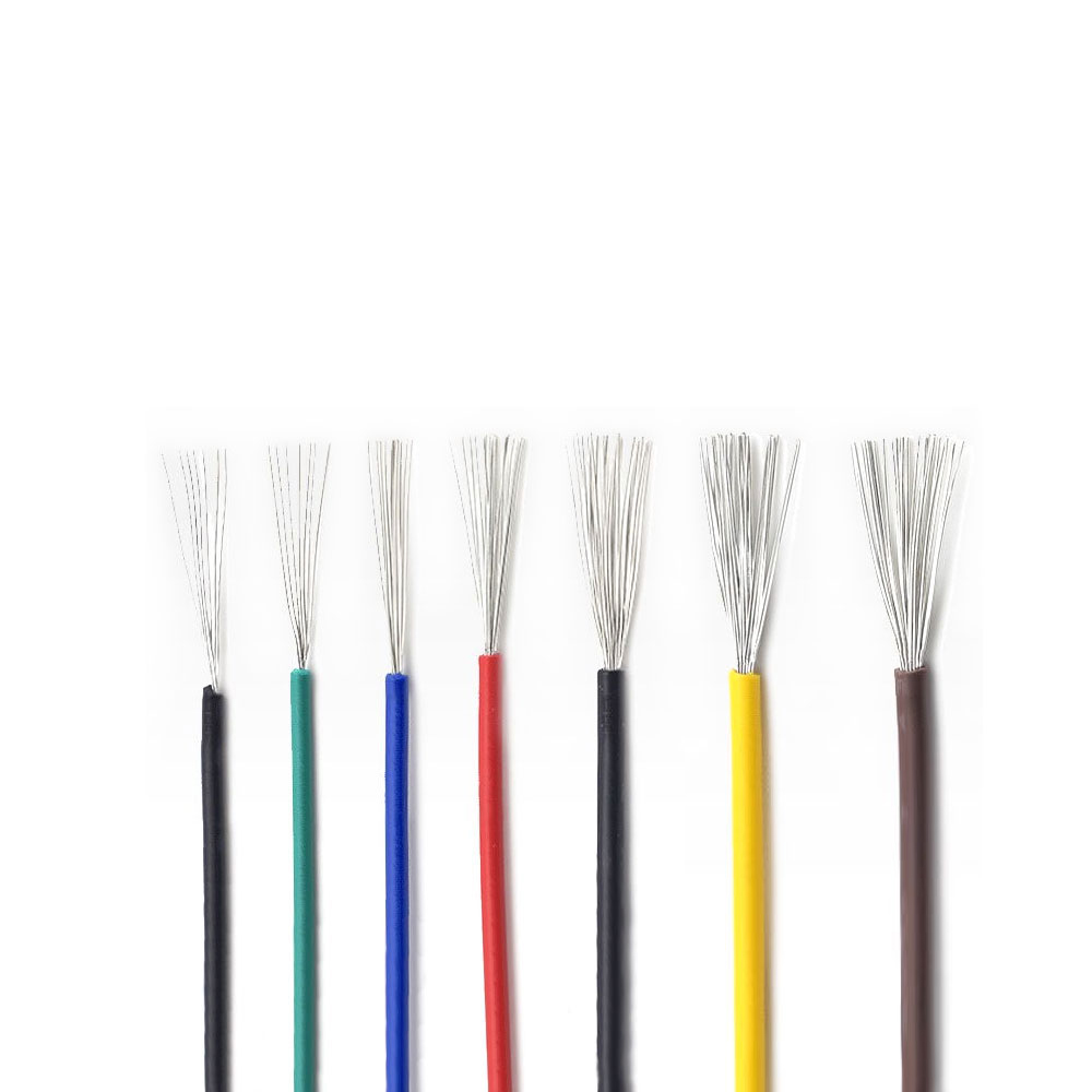
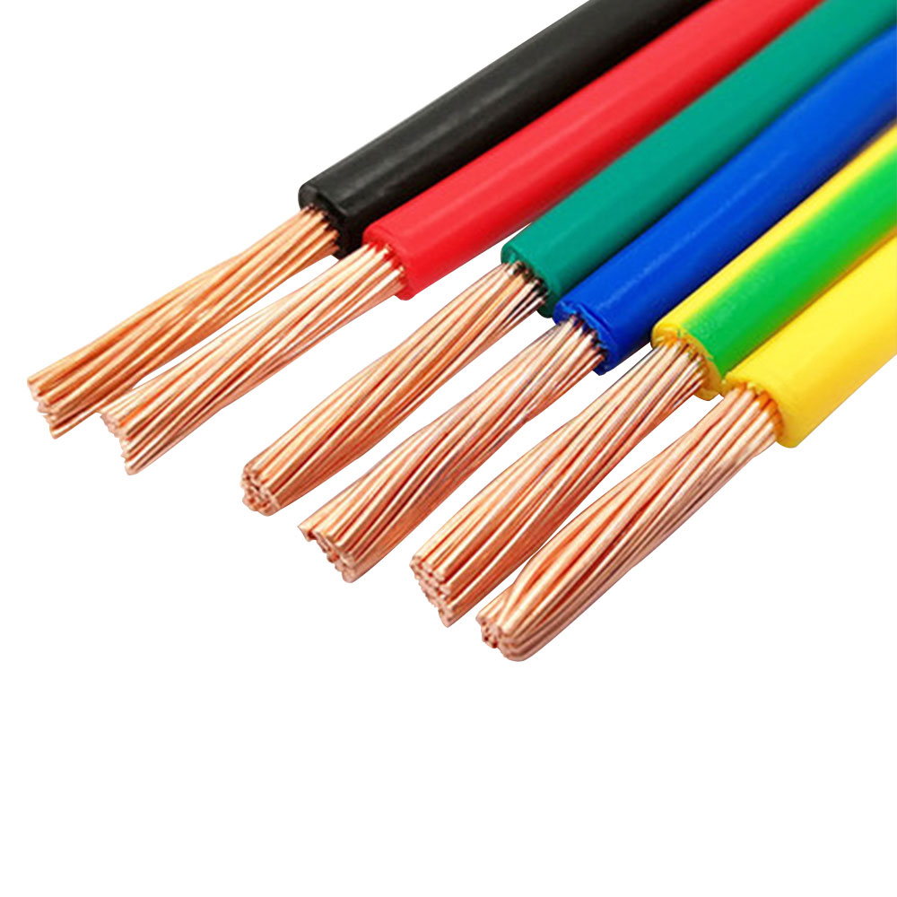
Color coding allows installers and maintenance technicians to identify power, control, signal, and feedback circuits. Clear identification is especially important in multi-core cable assemblies, where correct termination directly affects machine safety and commissioning time.
After insulation, the cores are assembled according to the cable design. Twisted pairs may be created for encoder or bus circuits, while power conductors and control cores are positioned to reduce interference and maintain a balanced structure.
Flexible filler materials or an inner sheath can be added to stabilize the core assembly. This helps prevent excessive movement between conductors, reduces internal friction, and creates a smoother foundation for the overall shield. The stranding pitch must be selected to balance flexibility with dimensional stability.
The overall shielding braid is applied using tinned copper wires arranged around the assembled core. Braid coverage, wire tension, angle, and uniformity must be monitored. A high-density braid requires precise process control so that the shield remains consistent along the full cable length.
Where individual pair shielding is required, aluminum foil and drain-wire arrangements may be applied before the overall copper braid. The completed shield should maintain electrical continuity and provide a reliable termination path. Testing may include shield resistance, continuity, coverage evaluation, and mechanical inspection.
The modified PVC outer sheath is extruded over the shield. The extrusion process must protect the braid without compressing the internal core excessively. Proper temperature, pressure, cooling, and line speed control help achieve stable outer diameter and smooth surface quality.
Outer diameter consistency is important for cable-carrier selection, connector compatibility, bending-radius calculations, and replacement planning. A standardized outer diameter can also simplify installation in existing machine channels and reduce maintenance downtime.
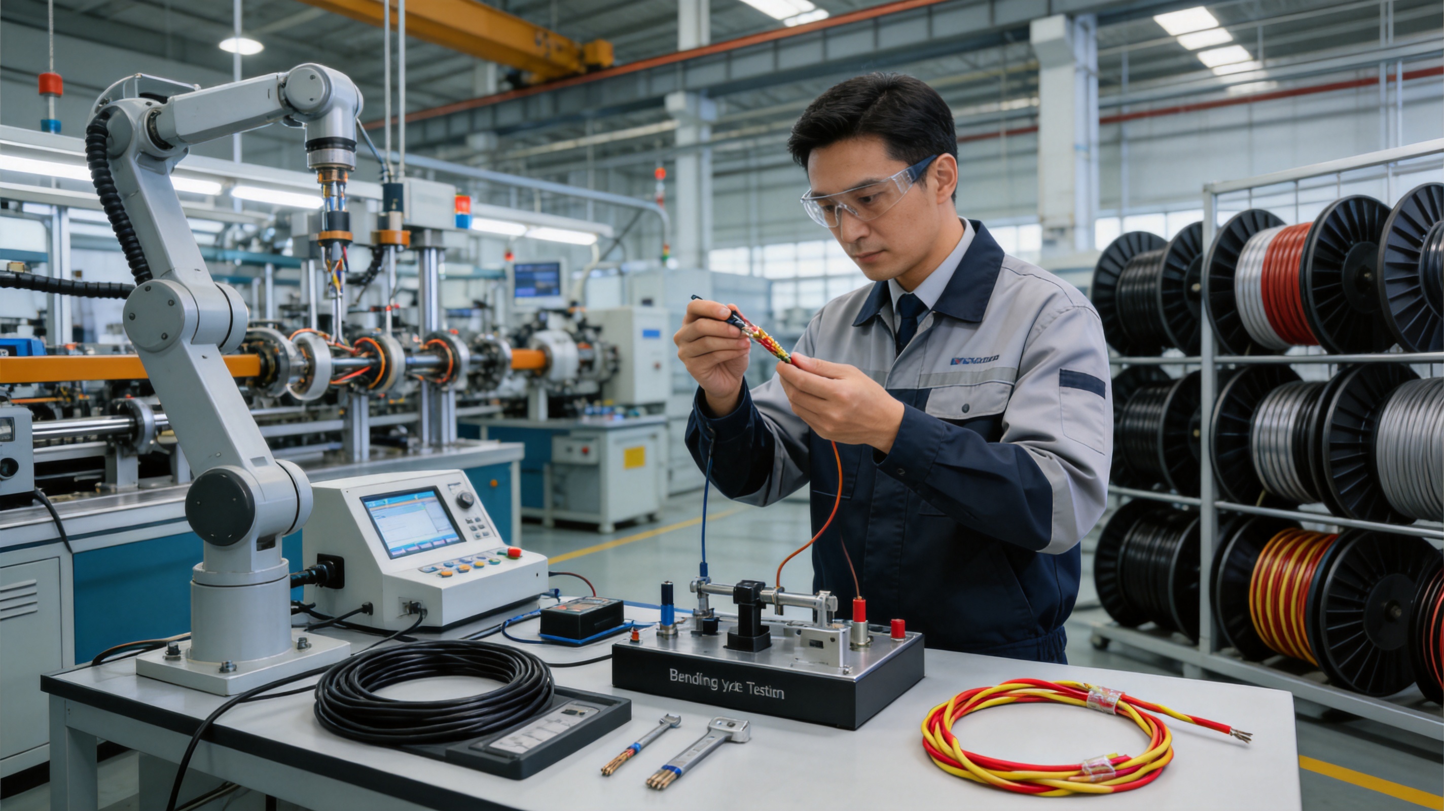
Quality assurance may include conductor resistance testing, insulation resistance testing, high-voltage testing, dimensional inspection, spark testing during insulation extrusion, shield continuity verification, and visual inspection. Where required, mechanical tests can evaluate bending, abrasion, torsion, and carrier movement.
The company provides product test reports and warranty support for standard cable models. Customers with special requirements can define test conditions in advance, including voltage, temperature, bending radius, travel distance, cycle count, chemical exposure, and communication performance.
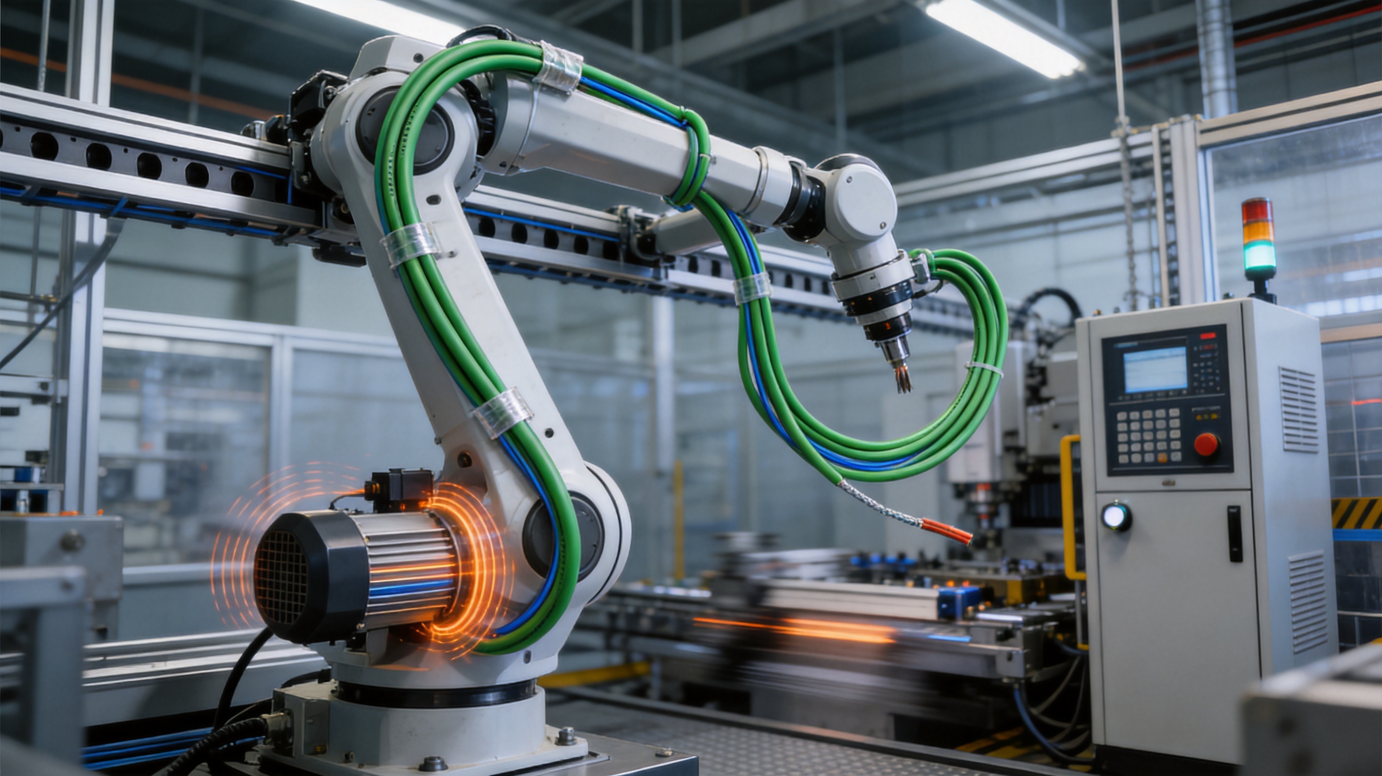
Robot cable requirements vary widely between machines. One system may require four power cores and two feedback pairs, while another may need a multi-core arrangement containing motor conductors, brake circuits, safety lines, encoder pairs, and industrial communication circuits.
Customization can address conductor cross-section, core count, insulation color, pair twisting, pair shielding, overall braid coverage, voltage rating, jacket material, outer diameter, marking, packaging, and delivery length. The manufacturer supports OEM and ODM development based on customer drawings or samples.
Technical engineers can assist with cable selection according to current, voltage, motion profile, installation space, environmental exposure, and connector requirements. This approach is useful when a standard cable does not fit the available cable carrier or when the customer wants to consolidate multiple cables into one integrated assembly.
Customization should begin with a complete application description. Important information includes the number and type of conductors, rated current, operating voltage, signal frequency, communication protocol, cable length, minimum bending radius, travel distance, movement speed, acceleration, torsion, temperature, oil exposure, and expected service life.
Six-axis robots require cables that can follow complex movement through multiple joints. Power, feedback, brake, and control signals may be routed through dress packs or integrated robot harnesses. The full copper shielding of the JQR-246P can help protect feedback and control circuits in areas where servo power cables and motor fields are present.
SCARA robots perform rapid repetitive movements in assembly, pick-and-place, packaging, and electronic manufacturing. Their high cycle rates place significant demands on cable flexibility and abrasion resistance. A compact multi-core configuration can simplify routing and reduce the number of separate cables moving with the robot.
Automotive plants commonly use robots for welding, painting, material handling, assembly, inspection, and fastening. These environments may include oil mist, coolant, vibration, high electrical noise, and continuous cable movement. The PVC sheath provides general oil and environmental protection, while the copper braid helps maintain signal reliability around servo equipment.
For welding applications, the cable must be evaluated carefully for heat, sparks, spatter, mechanical impact, and chemical exposure. The standard PVC construction may be suitable for protected routing but may require additional protective sleeves or a specialized welding-resistant cable in areas exposed directly to spatter.
Electronic assembly equipment often requires accurate low-voltage signals and stable communication. Noise from motors, switching power supplies, and high-speed actuators can affect inspection sensors, control signals, and data transmission. A layered shielded cable can help reduce unwanted interference while retaining the flexibility required for moving mechanisms.
Machine tools, transfer systems, and automated handling equipment frequently use cable carriers. These systems need cables that tolerate repeated reciprocating motion, coolant exposure, vibration, and limited installation space. The JQR-246P can be used for combined power and control functions where its voltage and environmental specifications match the machine requirements.
Correct installation is essential to achieving the expected life of any dynamic cable. The cable should be selected according to the actual movement profile rather than only the nominal electrical rating.
The cable carrier should have enough internal space to prevent compression. When several cables are installed together, they should be arranged so that heavy power cables do not crush smaller signal cables. The carrier should not force the cable into a radius smaller than the approved minimum.
Cables should be laid into the carrier without twisting. A cable removed from a reel should be unwound rather than pulled over the reel flange. Twisting introduced during installation can create hidden torsional stress that appears later as premature fatigue.
Fixed points should be located outside the active bending zone where possible. The cable should be secured in a way that transfers tensile forces to the jacket or designated strain-relief component rather than directly to the conductors or shield.
Connectors should be selected with appropriate strain relief and shielding termination. The braid should not be cut back unnecessarily, and the shield connection should be made according to the electrical system design. Poor shield termination can significantly reduce the benefit of a high-quality cable.
During commissioning, the cable path should be observed through the complete motion cycle. Look for buckling, rubbing, excessive lateral movement, sharp bending, compression, or contact with hot surfaces. Any abnormal movement should be corrected before continuous production begins.
Before ordering a robot cable, engineers should confirm the following requirements:
First, determine the number of conductors and their functions. Separate power, control, brake, safety, encoder, sensor, and communication requirements should be documented.
Second, calculate the conductor cross-sectional area based on current, voltage drop, ambient temperature, grouping, and installation method. A signal conductor should not be selected solely according to the physical space available.
Third, identify the required voltage rating and test voltage. Common options include 300/500 V and 0.6/1 kV, but the selected rating must match the equipment and applicable standards.
Fourth, define the movement profile. Include bending direction, bending radius, travel distance, speed, acceleration, cycle frequency, and torsion. A cable suitable for a straight carrier may not be suitable for a rotating robot joint.
Fifth, identify the electromagnetic environment. Note the presence of servo drives, variable-frequency drives, welding systems, high-current busbars, switching supplies, and nearby communication cables.
Sixth, specify the shielding arrangement. Some systems require an overall copper braid, individual pair shielding, or both. Shield coverage alone is not enough; grounding and termination must also be planned.
Seventh, evaluate the environment. Oil, coolant, chemicals, UV exposure, temperature, humidity, dust, welding spatter, and washdown conditions may require additional protection or a different jacket material.
Eighth, confirm the required service life and test standard. If the project requires a defined number of bending cycles, the manufacturer should confirm the test conditions and whether they match the actual application.
Anhui Zhishang Cable Technology Co., Ltd. combines product development, manufacturing, and technical support. Its facility in Xuancheng, Anhui Province, occupies approximately 5,000 square meters and employs more than 50 people, including quality engineers and research and development technicians with more than 10 years of industry experience.
The company operates more than 10 automated production lines and reports monthly output of up to 10 million meters. This capacity supports regular production of standard cable models while also providing a foundation for OEM and ODM projects.
Its production philosophy emphasizes full-core, full-length, pure-copper cable specifications, product testing, warranty support, and stable delivery. Standard products may be stocked for fast shipment, while customized products commonly require approximately 7 to 20 days of lead time, depending on design complexity, materials, quantity, and testing requirements.
The company follows national standards, relevant international standards, and industry benchmarks. It also provides product selection guidance and tailored cable design based on customer drawings or samples. This technical support can be valuable for automation integrators that need to replace an existing cable, adapt a cable to a new robot model, or combine several circuits into a custom assembly.
The manufacturer’s export experience includes customers in North America, Australia, Japan, and parts of Eurasia. Its stated certifications and compliance references include CE and RoHS requirements, while selected cable products are described as UL and CE certified. Certification should always be verified for the exact model and configuration ordered.
The purchase price of a cable is only one part of its total cost. A low-cost cable that fails frequently may create greater expense through production downtime, labor, replacement parts, troubleshooting, and possible damage to connectors or equipment.
The JQR-246P is designed to provide a balance between dynamic durability and cost. PVC is generally more economical than advanced specialty jacket materials, while the use of fine-stranded copper and a full copper braid provides performance beyond that of ordinary fixed-installation cable.
Integrated transmission can also reduce installation complexity. When power, control, and signal circuits can be combined into one suitable cable assembly, the number of separate cables, clamps, carrier compartments, and connector positions may be reduced. This can save space and simplify maintenance.
Standardized outer diameter and interface compatibility can support quick replacement. If a cable is available in a familiar size and compatible configuration, maintenance personnel can replace it without redesigning the complete routing system. Reduced replacement time can be particularly valuable in continuous production environments.
A responsible product evaluation must recognize the cable’s limitations. The JQR-246P is intended primarily for general industrial automation. It should not automatically be selected for every extreme application.
Where continuous high torsion, very small bending radii, severe outdoor exposure, extreme temperatures, aggressive chemicals, or direct welding spatter are present, a specialized cable may be required. Similarly, submerged applications, high-pressure washdown, and explosive atmospheres require additional system-level evaluation.
Dynamic life claims are dependent on test conditions. A stated cycle count does not guarantee the same life when the cable is installed at a smaller radius, subjected to higher acceleration, compressed in a carrier, or exposed to chemicals. The correct approach is to provide the manufacturer with complete application information and obtain confirmation for the intended design.
Shielding cannot compensate for poor grounding, incorrect connector assembly, unsuitable drive filters, or inadequate cabinet layout. The cable should be installed as part of a complete electromagnetic compatibility strategy.
Its main advantage is the combination of dynamic flexibility and full tinned-copper braided shielding. The shield helps suppress electromagnetic interference while the fine-stranded conductors and flexible PVC structure support repeated movement in industrial automation.
A full copper braid surrounds the cable core and creates a conductive barrier against external electromagnetic fields. It also helps reduce the radiation of internal noise. Because the braid is mechanically flexible, it is better suited to repeated bending than some shield arrangements intended primarily for fixed installation.
Yes. The cable can be configured as a multi-core assembly containing power, control, signal, encoder, feedback, and bus conductors. Sensitive pairs may receive individual shielding, while the complete assembly receives an overall copper braid.
The correct radius depends on the exact cable configuration and installation. Selected flexible designs may specify a minimum radius of 5 times the outer diameter, while mobile cable-carrier installations are commonly specified at 7.5 to 10 times the diameter. The approved value for the ordered model should always be followed.
Performance is configuration-dependent. Product information refers to millions of reciprocating movements, commonly in the range of more than 2 million to 5 million under specified test conditions, with selected designs or application tests referring to up to 10 million cycles. Actual life depends on radius, speed, acceleration, torsion, carrier alignment, and environment.
The modified PVC sheath provides resistance to oil, grease, coolant, weak acids, and weak alkalis for general industrial conditions. The exact resistance depends on the chemical, temperature, exposure duration, and mechanical stress. Severe chemical or washdown applications should be evaluated separately.
It can be suitable for encoder and feedback circuits when the conductor arrangement, pair geometry, shielding, voltage, and communication requirements are correctly specified. Individual pair shielding may be used for critical feedback circuits, and the complete system must use proper grounding and termination.
Yes. Customization may include conductor size, core count, color coding, pair twisting, individual shielding, overall braid coverage, voltage rating, sheath color, outer diameter, marking, and packaging. OEM and ODM development can be based on technical drawings or samples.
Selected products are described as UL and CE certified, with flame-retardant performance designed to comply with IEC 60332-1-2 requirements. Certification should be confirmed for the exact cable model, construction, and production batch required for a project.
No. The cable is suitable for many general automation and robot applications, but every joint has a different movement profile. High-torsion or highly complex multi-axis joints may require a cable specifically tested for that duty. The robot manufacturer’s routing requirements and the cable supplier’s application guidance should be followed.
Provide the number and size of conductors, voltage, current, signal types, communication protocol, cable length, outer diameter limit, bending radius, travel distance, movement speed, acceleration, torsion, temperature, chemical exposure, required certifications, and expected delivery quantity.
Custom technical support can help match the cable to the actual machine rather than forcing the machine to use an unsuitable standard cable. Engineers can optimize core arrangement, shielding, conductor size, jacket material, and outer diameter to improve installation, reliability, and total project cost.
The JQR-246P PVC Robot Cable is designed for automation systems that require reliable power and signal transmission during repeated movement. Its full tinned-copper braided shield is the central performance feature, helping protect sensitive circuits from electromagnetic interference and reducing crosstalk between power and signal conductors.
Fine-stranded oxygen-free copper conductors, flexible insulation, controlled core stranding, optional individual pair shielding, and a modified PVC outer sheath provide a balanced construction for general industrial environments. Compared with unshielded flexible cables, fixed-installation cables, or basic foil-only designs, the product offers stronger support for dynamic signal integrity. Compared with more expensive specialty cables, it provides a practical cost-effective option for many standard automation applications.
The manufacturer’s automated production lines, research and development capabilities, quality-control processes, customization support, and production capacity strengthen the product’s commercial value. However, correct selection and installation remain essential. Bending radius, torsion, cable-carrier design, grounding, connector termination, temperature, chemical exposure, and movement profile must all be considered.
When specified and installed correctly, a full copper shielded PVC robot cable can contribute to lower communication error rates, longer maintenance intervals, easier replacement, and more stable operation of robotic equipment. It is a suitable solution for many industrial automation projects seeking dependable dynamic performance without the cost of an extreme-environment cable.
1. International Electrotechnical Commission, IEC 60332-1-2, Tests on Electric and Optical Fibre Cables under Fire Conditions.
2. International Electrotechnical Commission, IEC 60811 Series, Electric and Optical Fibre Cables: Test Methods for Non-Metallic Materials.
3. International Electrotechnical Commission, IEC 60228, Conductors of Insulated Cables.
4. Industrial automation cable design principles for dynamic bending, shielding, and cable-carrier installation.
5. Manufacturer technical information for flexible PVC robot cable construction, conductor arrangements, shielding, and application requirements.
6. General engineering guidance for electromagnetic compatibility in servo systems, encoder feedback circuits, and industrial communication networks.
7. General cable-carrier installation practices for dynamic cables, including bending-radius control, strain relief, routing, and movement inspection.

We firmly believe that good cables are not only a competition of materials, but also a reflection of craftsmanship, quality, and responsibility.

Links
Product
Send Inquiry
No. 29 Sankeshu Road, Xuanzhou District, Xuancheng City, Anhui Province, China
+86-18621104555/+86-563-2622999
 Electrical Cable Manufacturer
OEM/ODM Wire and Cable Solutions
Electrical Cable Manufacturer
OEM/ODM Wire and Cable Solutions
 English
 Español
 عربى
عربى
 русский