
Get more content that can help you
Content
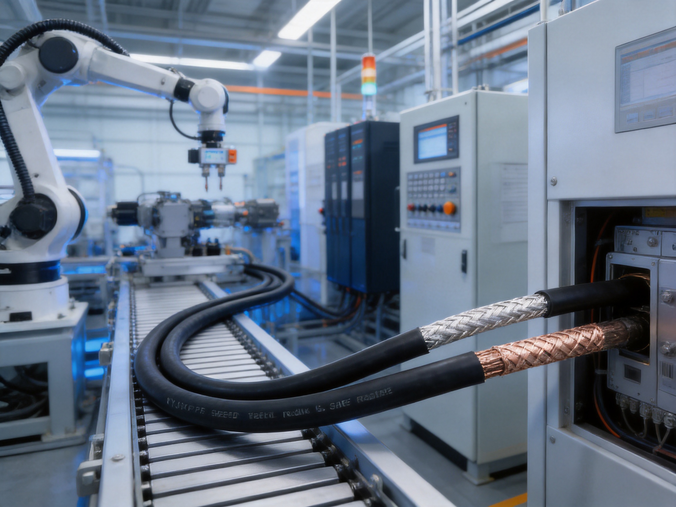
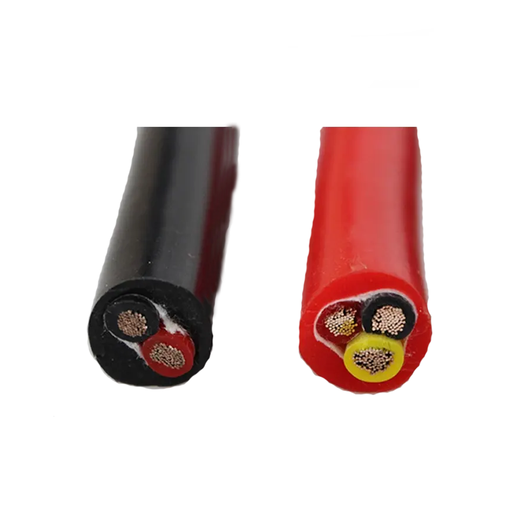
Modern industrial systems depend on control cables that can carry electrical signals reliably while withstanding heat, movement, electromagnetic interference, and demanding installation conditions. In automated production lines, testing equipment, mobile machinery, and instrument connections, cable performance directly affects system stability. A cable that becomes brittle, overheats, loses insulation resistance, or allows electromagnetic interference to distort signals can create downtime, maintenance costs, and safety risks.
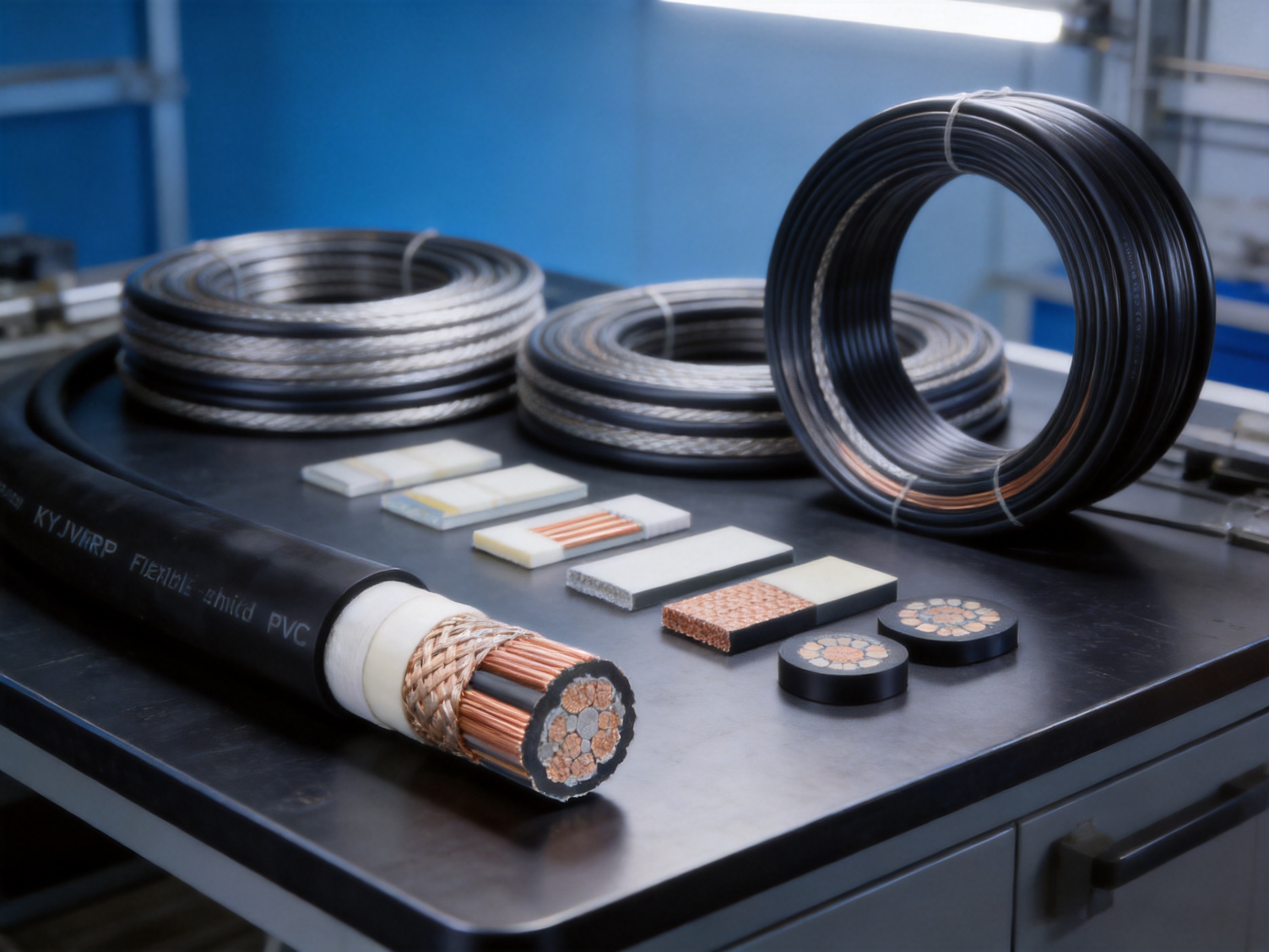
KYJVRP is a flexible shielded control cable developed for applications that require stable electrical performance, high-temperature capability, and dependable protection against interference. It combines fine-stranded annealed copper conductors, cross-linked polyethylene insulation, copper braid shielding, and a protective PVC sheath. This construction provides a practical balance between flexibility, electrical reliability, mechanical endurance, temperature resistance, and cost control.
With a rated voltage of 450/750V, a long-term operating temperature of up to 90°C, and a copper braid shield with at least 80% coverage, KYJVRP is designed for control and signal wiring in industrial environments. It is especially suitable where cables must move repeatedly or operate near motors, inverters, switching devices, sensors, and other potential sources of electromagnetic interference.
This article examines the construction, performance, advantages, manufacturing strengths, installation requirements, and application value of KYJVRP control cable. It also explains how a modern cable manufacturer supports consistent production, customization, quality assurance, and supply reliability for industrial customers.
KYJVRP is a flexible shielded control cable with cross-linked polyethylene insulation and a copper braid shield. The “K” designation identifies a control cable family, while the “YJ” structure indicates cross-linked polyethylene insulation. The “V” generally refers to a PVC sheath, and “R” indicates a flexible conductor structure. The “P” identifies the shielding arrangement.
The cable is manufactured with fine-stranded copper conductors rather than rigid or lightly stranded conductors. Fine stranding reduces the bending stress experienced by individual copper wires when the cable is routed through compact spaces or moved repeatedly. This makes the cable more suitable for mobile equipment, movable assemblies, automated machinery, and connection points exposed to recurring flexing.
Each conductor is insulated with XLPE. Compared with ordinary PVC insulation, XLPE provides improved thermal capability, stronger resistance to thermal deformation, low dielectric loss, and stable insulation performance over extended service. The insulated cores are assembled into a cable structure and covered by a copper braid shield. The shield helps reduce the influence of external electromagnetic fields and limits the radiation of interference from the cable itself.
A PVC outer sheath protects the inner construction from moisture, abrasion, handling damage, and general industrial exposure. The standard structure is intended for indoor environments and mild industrial conditions. For applications requiring special fire, smoke, chemical, oil, or halogen-free performance, additional structural options may be considered during product design.
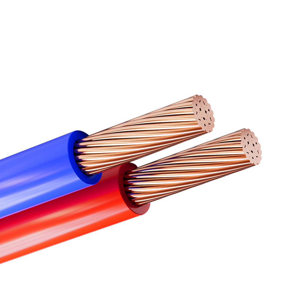
The conductor is made from stranded annealed copper with a fine-stranding design. Copper is selected for its high electrical conductivity, dependable connection performance, and compatibility with common control terminals and industrial connectors. Annealing improves flexibility by reducing the hardness of the copper wires.
The available conductor cross-section range is 0.5 mm² to 6.0 mm². This range covers many common control, instrumentation, auxiliary power, relay, sensor, and actuator requirements. Depending on the circuit design, the cable can be supplied with two to thirty-seven cores.
Fine stranding is especially valuable in installations where the cable is routed around moving machine parts. A cable with fewer, thicker strands may remain electrically functional but can experience higher localized stress during repeated bending. By distributing bending across a larger number of smaller wires, the conductor structure supports improved flexibility and longer mechanical service life.
Cross-linked polyethylene insulation is a key feature of KYJVRP. Cross-linking changes the molecular structure of polyethylene and improves its ability to maintain mechanical and electrical properties at elevated temperatures. The insulation supports a long-term conductor operating temperature of 90°C.
XLPE also offers good insulation resistance and low dielectric loss. These properties help maintain signal quality and reduce the possibility of leakage currents or insulation-related instability. The specified insulation resistance is at least 1000 MΩ·km at 20°C, demonstrating the high resistive performance expected from a carefully manufactured insulation system.
The standard insulation thickness ranges from 0.6 mm to 1.2 mm, depending on the conductor size and cable design. Correct thickness control is important. Excessively thin insulation can reduce electrical and mechanical protection, while excessive thickness may increase cable diameter, stiffness, and material consumption. Automated extrusion and dimensional inspection help maintain the intended balance.
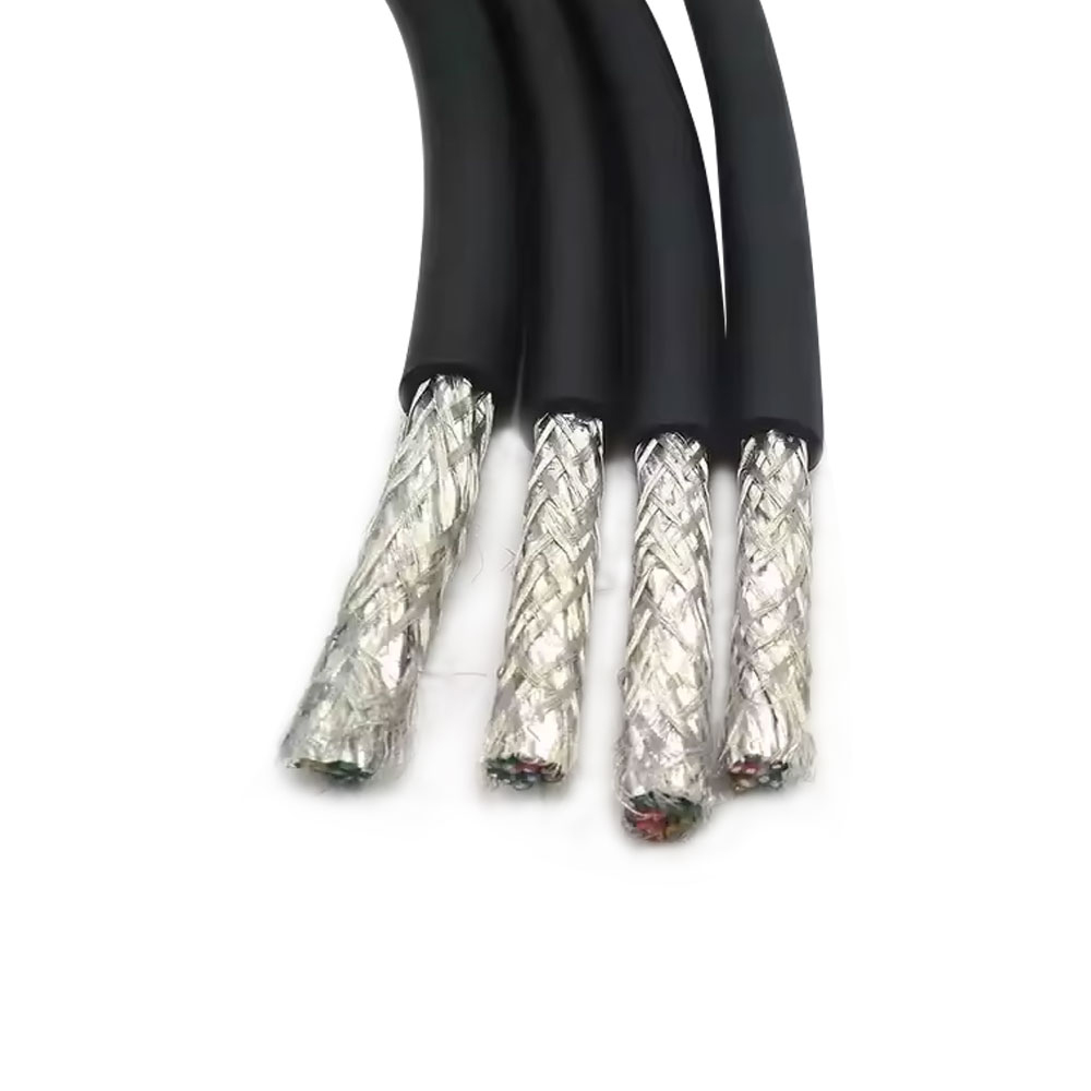
The copper braid shield provides protection against electromagnetic interference. The shield has a coverage of at least 80%, creating a conductive barrier around the insulated cores. It is particularly useful in environments containing variable-frequency drives, servo motors, relays, switching power supplies, contactors, and other equipment that can generate electrical noise.
Shielding effectiveness depends on more than the presence of copper. Braid coverage, braid angle, electrical continuity, contact quality, grounding method, and cable routing all influence the final result. A properly manufactured braid shield with consistent coverage offers a more dependable interference-control solution than an irregular or incomplete shield.
The stated shielding attenuation factor is no greater than 0.8 at 1 MHz. This performance supports the cable’s intended role in sensitive control and instrumentation systems. Correct termination is also essential. The shield should be connected according to the equipment manufacturer’s grounding instructions and the electromagnetic compatibility requirements of the installation.
The outer sheath is made from PVC and provides the first line of mechanical and environmental protection. It helps resist moisture, ordinary abrasion, handling damage, and contact with surfaces during installation. PVC also provides a practical and economical sheath solution for indoor industrial applications and mild environmental conditions.
The sheath thickness ranges from 1.0 mm to 1.8 mm. As with insulation thickness, controlled sheath dimensions support consistent diameter, bending behavior, protection, and stripping performance. A sheath that is too thin may be vulnerable to damage, while an unnecessarily thick sheath can make the cable difficult to route.
The standard temperature range is -15°C to +90°C for fixed installation and -5°C to +90°C for flexible installation. The lower flexible-installation limit reflects the fact that polymeric materials generally become less flexible at low temperatures. Installation below the recommended range should be evaluated carefully, especially when repeated movement is expected.
| Item | Specification |
|---|---|
| Product type | Flexible shielded control cable |
| Conductor | Stranded annealed copper conductor with fine stranding |
| Cross-section range | 0.5 mm² to 6.0 mm² |
| Number of cores | 2 cores to 37 cores |
| Rated voltage | 450/750V |
| Test voltage | 3.0kV AC for 1 minute |
| Insulation material | Cross-linked polyethylene |
| Insulation thickness | 0.6 mm to 1.2 mm |
| Shielding structure | Copper braid shield |
| Shield coverage | At least 80% |
| Sheath material | Polyvinyl chloride |
| Sheath thickness | 1.0 mm to 1.8 mm |
| Fixed installation temperature | -15°C to +90°C |
| Flexible installation temperature | -5°C to +90°C |
| Long-term operating temperature | Up to 90°C |
| Minimum bending radius | At least 8 times the cable outer diameter for fixed installation; at least 12 times for flexible installation |
| Insulation resistance | At least 1000 MΩ·km at 20°C |
| Shielding attenuation factor | No greater than 0.8 at 1 MHz |
| Bending endurance | At least 10,000 cycles for flexible installation |
| Capacitance | No greater than 170 nF/km |
| Short-circuit temperature | Conductor temperature not exceeding 250°C for a maximum of 5 seconds |
| Tensile strength | At least 12 N/mm² |
| Thermal deformation | Passes a 150°C, 4-hour thermal deformation test |
One of the most important differences between KYJVRP and ordinary PVC-insulated flexible control cables is the use of XLPE insulation. Standard PVC control cable constructions may be suitable for normal ambient conditions, but their thermal capability can be more limited. Continuous operation near heat sources may accelerate aging, hardening, deformation, and insulation deterioration.
KYJVRP supports long-term operation at 90°C. This makes it more appropriate for high-temperature control cabinets, production equipment near heaters, testing systems, motor areas, and industrial machinery where cable temperature may rise above ordinary room temperature. The higher temperature rating also provides additional design margin when actual operating conditions vary.
Temperature resistance does not mean the cable can be installed directly against unlimited heat sources. The complete installation must consider ambient temperature, conductor loading, ventilation, proximity to hot surfaces, bending conditions, and the temperature rating of terminals and connected equipment. Nevertheless, the XLPE insulation gives system designers a stronger starting point than conventional lower-temperature insulation.
Unshielded control cables can be affected by electromagnetic fields produced by power cables, motors, switching devices, and variable-frequency drives. Interference may appear as unstable sensor readings, false switching, communication errors, irregular actuator behavior, or unexplained control-system alarms.
The copper braid shield in KYJVRP creates a continuous conductive layer around the insulated cores. With coverage of at least 80%, the shield is designed to reduce coupling between external noise sources and the control circuits. It also helps limit the emission of electrical noise from the cable.
Compared with simple unshielded flexible cables, the shielded structure is a significant advantage in sensitive applications. Compared with low-coverage or poorly controlled shields, a consistent copper braid can provide more predictable performance. The final result still depends on correct grounding, separation from high-power circuits, and appropriate connector design.
Many control cables are installed in fixed positions and are not designed for continuous movement. When such cables are used in moving machinery, they may develop conductor fatigue, sheath cracks, or insulation damage. KYJVRP addresses this requirement with fine-stranded copper conductors and a flexible cable construction.
The product is specified for at least 10,000 bending cycles in flexible installation. This makes it suitable for movable component connections, automated production equipment, inspection machines, and other applications involving repeated routing changes. The cable should still be installed with the recommended bending radius and without twisting, crushing, or unsupported hanging sections.
Flexibility also improves installation efficiency. Cables can be routed through compact control cabinets, around machine frames, and into equipment junction boxes with less force. Easier routing can reduce installation time and decrease the risk of damage caused by excessive pulling or sharp bending.
Control cables carry more than simple on-and-off signals. They may be used for sensor outputs, analog signals, feedback circuits, interlocks, relay control, instrumentation, and auxiliary power. These applications can be sensitive to insulation resistance, capacitance, dielectric loss, and external interference.
KYJVRP combines XLPE insulation, copper conductors, controlled capacitance, and shielding to support stable signal and control performance. The maximum specified capacitance is 170 nF/km. Low dielectric loss and strong insulation resistance help reduce unwanted electrical interaction between cores and between the conductors and shield.
The cable is tested at 3.0kV AC for one minute. This test verifies the insulation system’s ability to withstand a defined electrical stress during production inspection. A successful test does not replace correct system design, but it provides important evidence of insulation integrity before shipment.
High-performance cable does not always need to use the most expensive materials or the most complex construction. KYJVRP is designed to balance performance and cost by combining a proven copper conductor, XLPE insulation, copper braid shielding, and a PVC sheath.
The construction provides more temperature capability and interference protection than basic flexible control cable, while remaining more economical and easier to process than specialized cables designed for extreme chemical, fire, radiation, or outdoor conditions. This makes it a practical choice for customers seeking improved performance without unnecessary specification escalation.
Automated production lines include sensors, actuators, motors, control panels, safety circuits, and programmable controllers. Cables installed in these systems often pass close to power conductors and switching equipment. KYJVRP can be used for control connections where signal stability, flexibility, and interference reduction are important.
The cable is suitable for connections between sensors and control cabinets, relay circuits, valve controls, machine interfaces, and movable assemblies. Its 450/750V rating gives it flexibility for many control and auxiliary power arrangements, subject to the requirements of the specific circuit and applicable installation standards.
Testing equipment can be sensitive to electrical noise. Small disturbances may influence measurement results or cause false readings. A shielded control cable helps protect low-level signals from nearby motors, switching components, and laboratory equipment.
The fine-stranded construction also supports compact equipment layouts. Cables can be routed through instrument panels and test fixtures without placing excessive force on terminals. XLPE insulation provides additional thermal margin when testing involves heated components or prolonged operation.
Robotic equipment, indexing machines, movable tables, machine doors, and adjustable fixtures may require cables to flex during operation. KYJVRP is designed for flexible installation and can withstand at least 10,000 bending cycles under appropriate conditions.
In these applications, cable life depends on the movement profile. The installer should determine the direction of travel, cycle frequency, bend radius, acceleration, support method, and exposure to abrasion. The cable should not be twisted along its length, and it should be protected from sharp edges and excessive tension.
Industrial instruments may include pressure sensors, temperature transmitters, flow meters, position sensors, and monitoring devices. These circuits often require stable signal transmission over a defined distance. The shield helps reduce interference, while the low-loss insulation system supports electrical consistency.
When connecting instrumentation, the shield termination method should be selected based on the system grounding design. In some applications, the shield is grounded at one end to reduce ground-loop risk. In other systems, a full shield connection may be required for high-frequency interference control. The equipment designer should establish the appropriate method.
KYJVRP can be used in areas where cable temperatures approach the normal limits of standard flexible PVC cables. Examples may include heating equipment controls, industrial ovens with separated wiring zones, thermal testing machines, and production equipment located near hot surfaces.
The cable should not be treated as a substitute for heat shielding or thermal separation. Where temperatures may exceed 90°C, a detailed thermal assessment is required. In normal high-temperature control conditions within the product rating, however, XLPE insulation offers a stronger and more reliable solution than ordinary low-temperature insulation.
KYJVRP Stable electrical performance Control Cable
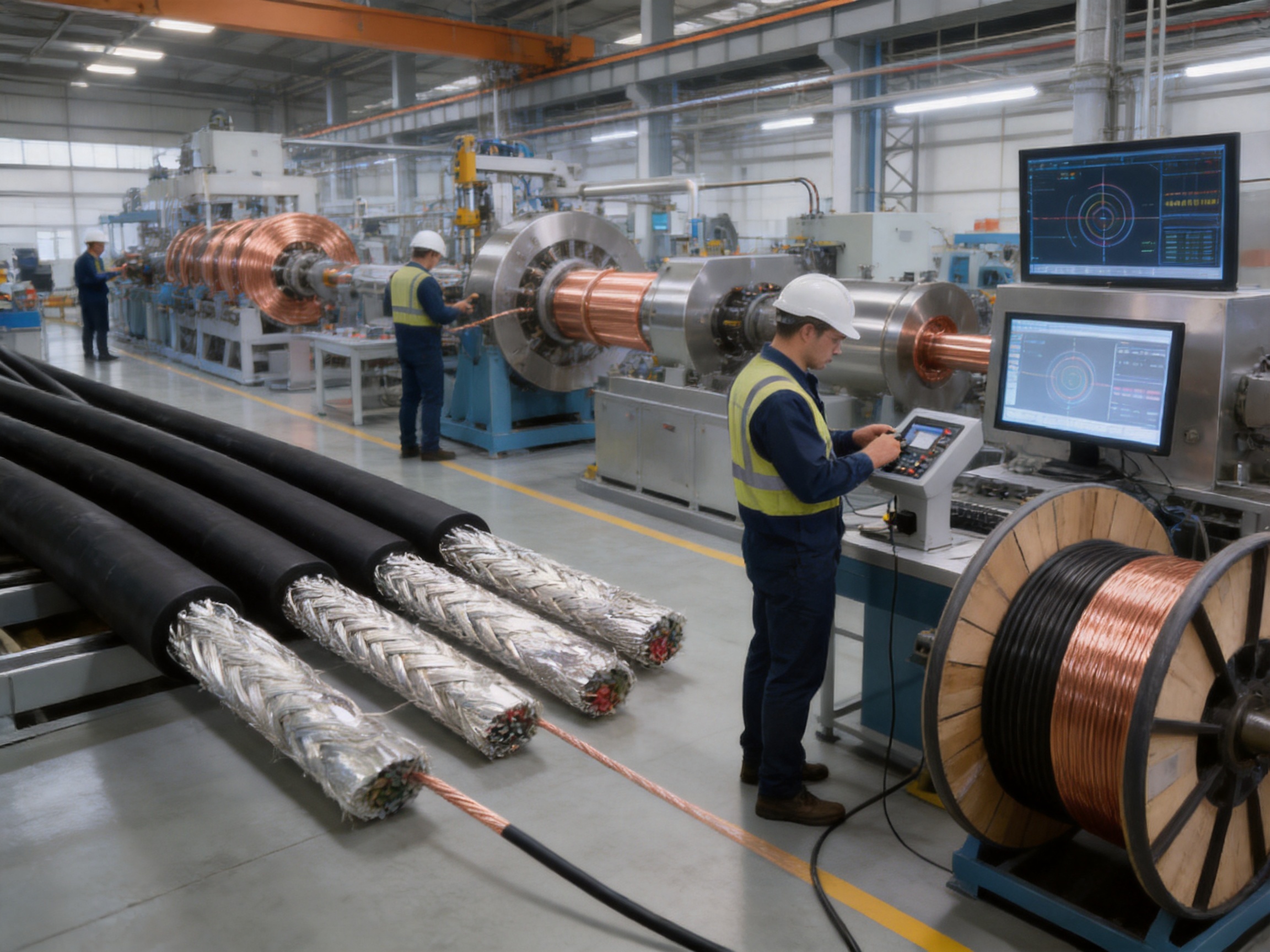
Manufacturing begins with the selection and preparation of annealed copper. Incoming copper is evaluated for conductivity, surface condition, diameter consistency, and mechanical suitability. The copper wires are then stranded according to the required cross-section and flexibility grade.
Fine stranding requires accurate control of wire tension, pitch, alignment, and take-up speed. If tension is inconsistent, the finished conductor may have uneven compactness or localized stress. Modern stranding equipment helps maintain uniform geometry and repeatable flexibility across production batches.
The stranded conductor passes through an extrusion line where XLPE insulation is applied. Extrusion parameters include material temperature, line speed, pressure, cooling conditions, and concentricity. A stable extrusion process helps ensure that the insulation remains centered around the conductor.
Online diameter measurement can monitor the insulation during production. If the diameter moves outside the process window, operators can make immediate adjustments. This reduces the risk of thin spots, uneven insulation, or excessive material accumulation.
After extrusion, the insulation undergoes the required cross-linking process. Proper cross-linking is important because it determines the final thermal, mechanical, and electrical properties of the XLPE. The process must be controlled to achieve reliable performance without damaging the conductor or creating defects in the insulation.
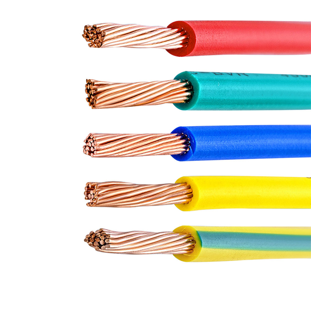
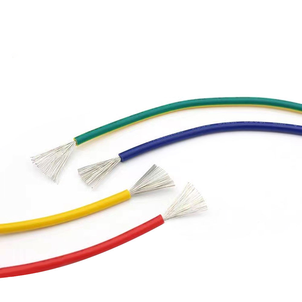
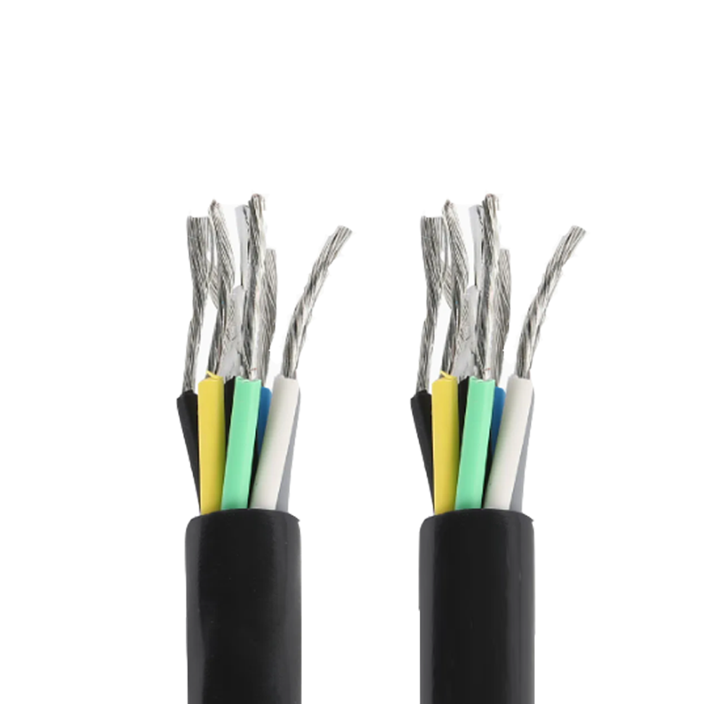
Control cables may contain from two to thirty-seven cores. Clear core identification is essential for efficient installation and maintenance. Depending on the design, cores may be identified through color coding, numbering, printing, or a combination of methods.
The insulated cores are assembled with controlled lay length and tension. Proper assembly reduces internal stress, supports consistent cable geometry, and helps the finished cable bend smoothly. Poor assembly can result in uneven diameter, core displacement, or difficulties during stripping and termination.
The copper braid is applied over the assembled insulated cores. Braid machines control the number of carriers, wire tension, braid angle, and coverage. These parameters affect flexibility, shield continuity, and electromagnetic performance.
At least 80% shield coverage is specified for KYJVRP. Production inspections can verify braid condition, coverage, continuity, and mechanical integrity. A stable braid structure is important because gaps, loose strands, or excessive tension may reduce shielding performance or make the cable less flexible.
The PVC sheath is applied over the shielded core assembly. The sheath must fully encapsulate the internal structure while maintaining the specified outer diameter and surface quality. Extrusion temperature, die alignment, cooling, and line speed are controlled to produce a smooth and uniform finish.
The sheath material can be selected or adjusted according to the intended application requirements. Standard construction is suitable for indoor and mild industrial environments. Depending on project needs, additional options such as flame retardancy or halogen-free materials may be evaluated as part of a customized design.
Finished cable is tested through a combination of electrical, dimensional, material, and mechanical inspections. Typical checks include conductor resistance, insulation resistance, withstand voltage, outer diameter, sheath thickness, shield continuity, visual appearance, and marking quality.
The product is specified to withstand a 3.0kV AC test for one minute. Insulation resistance is evaluated against the specified minimum value at 20°C. Additional tests address thermal deformation, tensile strength, bending endurance, capacitance, and shielding performance.
Testing is important not only for final acceptance but also for process improvement. Results can reveal trends in extrusion, stranding, braiding, or material behavior. A manufacturer with effective quality management uses test data to identify root causes and improve future production stability.
Anhui Zhishang Cable Technology Co., Ltd. integrates research and development, manufacturing, and sales. Its production base covers approximately 5,000 square meters and includes ten automated production lines. The company reports a monthly output capacity of up to 10 million meters, providing a foundation for both standard product supply and project-based production.
The company employs more than fifty people, including quality engineers and research and development technicians with more than ten years of industry experience. Experienced technical personnel are important for control cable production because cable performance depends on the interaction of conductor construction, insulation materials, shielding design, sheath formulation, and processing conditions.
Production capacity is valuable when it is supported by process discipline. Automated equipment can improve repeatability, while trained engineers can respond to changes in product design, customer drawings, installation conditions, and compliance requirements. This combination enables more consistent manufacturing than a purely manual or loosely controlled process.
The company provides full-core and full-length pure copper specifications for standard cable models, along with product test reports and warranty support. Standard products may be stocked for faster shipment, while customized products typically require a lead time of seven to twenty days. Actual delivery depends on product structure, quantity, material availability, testing requirements, and packaging arrangements.
For customers with special requirements, the engineering team supports OEM and ODM development based on drawings or samples. Possible customization areas include conductor cross-section, core count, color identification, overall diameter, shielding configuration, sheath material, marking, packaging, and special performance options.
The company serves industrial automation, weak-current engineering, intelligent manufacturing, appliance equipment, power engineering, and related fields. Its products are supplied to markets including the United States, Canada, Australia, Japan, and parts of Eurasia. International supply requires attention to documentation, product consistency, packaging, communication, and customer-specific technical expectations.
Different control systems require different numbers of signal and power circuits. KYJVRP can be configured from two to thirty-seven cores, with cross-sections from 0.5 mm² to 6.0 mm². This supports compact sensor wiring as well as larger control and auxiliary power circuits.
Customers should provide load current, voltage, installation length, ambient temperature, voltage drop limits, and terminal requirements when selecting the conductor size. A larger conductor is not automatically better because it may increase cable diameter and reduce flexibility. Correct sizing is based on the complete electrical and mechanical design.
The standard product uses a copper braid shield with at least 80% coverage. For projects with special interference conditions, the shielding arrangement may be reviewed. Engineers may evaluate braid coverage, additional drain conductors, foil layers, grounding requirements, and separation from power circuits.
The correct shielding solution depends on the frequency and strength of the interference, the signal type, cable length, equipment design, and grounding architecture. A customized cable should therefore be specified together with the system’s electromagnetic compatibility objectives.
The standard PVC sheath is appropriate for many indoor and mild industrial installations. Some projects may require improved flame retardancy, low smoke, halogen-free construction, oil resistance, chemical resistance, or enhanced outdoor durability.
These options may affect flexibility, diameter, temperature performance, cost, and processing requirements. Customers should identify the applicable environmental and safety standards before production so that the cable construction can be selected correctly rather than modified after installation.
Clear marking can reduce installation errors and simplify maintenance. Options may include customer part numbers, sequential meter markings, core identification, voltage rating, manufacturer information, and production batch information.
Packaging can also be adapted to project needs. Cable may be supplied on reels, drums, coils, or other formats depending on length, weight, transportation conditions, and installation equipment. Proper packaging protects the sheath and prevents excessive bending during shipment.
Before installation, inspect the cable for cuts, crushing, moisture ingress, deformation, or damage to the outer sheath. Confirm the product identification, core count, conductor size, voltage rating, and temperature requirements against the project documentation.
For fixed installation, maintain a minimum bending radius of at least eight times the cable outer diameter. For flexible installation, maintain a minimum bending radius of at least twelve times the cable outer diameter. The flexible-installation radius is larger because repeated movement produces greater mechanical stress.
Do not pull the cable by the shield, individual conductors, or core ends. Use suitable pulling equipment and avoid exceeding the manufacturer’s recommended pulling force. During installation, prevent the cable from twisting, knotting, scraping against sharp edges, or becoming trapped under heavy equipment.
When the cable is used in a moving application, ensure that the movement is guided and supported. The cable should follow a controlled path rather than being forced to bend randomly. Repeated torsion can shorten service life even when the bending radius is acceptable.
Keep control cables separated from high-power cables wherever practical. If crossing is necessary, a controlled crossing angle can reduce parallel coupling. Avoid routing the cable directly beside variable-frequency motor cables for long distances unless the system design includes appropriate electromagnetic compatibility measures.
Terminate the copper braid shield carefully. Remove only the necessary sheath length, avoid cutting shield wires, and use a termination method compatible with the connector or control cabinet. Poor shield termination can reduce the benefit of the braid and create a potential source of noise or mechanical weakness.
Do not exceed the 90°C long-term operating temperature. The temperature of the conductor depends on current, ambient conditions, installation method, heat dissipation, and the number of loaded cores. Where several cables are grouped together, derating may be required.
Regular inspection can identify problems before they cause control-system failures. Maintenance personnel should check for sheath abrasion, discoloration, cracking, loose supports, excessive bending, exposed braid, and signs of overheating near terminals.
In moving applications, inspect the travel path and cable support system. A cable may fail prematurely because of an installation problem rather than a material defect. Common causes include a bend radius that is too small, twisting, unsupported weight, repeated contact with a sharp edge, or movement outside the intended travel direction.
Electrical maintenance may include insulation resistance testing, shield continuity testing, conductor resistance checks, and functional verification of connected circuits. Testing should be performed according to the equipment manufacturer’s procedures and applicable safety rules.
Service life depends on temperature, movement frequency, chemical exposure, mechanical stress, electrical loading, and installation quality. KYJVRP’s specified 10,000-cycle bending endurance provides a useful design reference, but it should not be interpreted as a universal service-life guarantee for every movement profile.
Product selection is often based on a comparison of electrical performance, mechanical capability, environmental suitability, lead time, technical support, and total ownership cost. KYJVRP offers a combination that is difficult to achieve with basic control cable: flexible fine-stranded copper conductors, 90°C XLPE insulation, copper braid shielding, stable dielectric properties, and a practical PVC sheath.
Against conventional unshielded cables, KYJVRP provides stronger interference protection. Against ordinary PVC-insulated cables, it provides higher long-term thermal capability. Against rigid or lightly stranded cables, it offers better installation flexibility. Against highly specialized extreme-environment cables, it may offer a more cost-effective option where the application does not require the highest level of chemical, fire, or outdoor resistance.
The product is also supported by a manufacturing organization capable of standard production and customization. Access to engineering support, test reports, OEM and ODM services, standard inventory, and defined production lead times can reduce procurement risk for industrial projects.
Its competitive value is therefore not limited to a single specification. The strength lies in the complete combination of materials, construction, manufacturing control, application support, and supply capability.
When evaluating KYJVRP for a project, begin by defining the cable’s electrical function. Confirm whether the cable will carry control signals, sensor outputs, relay circuits, auxiliary power, or a combination of these. Record the nominal voltage, current, frequency, signal type, circuit length, and allowable voltage drop.
Next, evaluate the installation environment. Important factors include ambient temperature, proximity to heat sources, humidity, abrasion, chemical contact, oil exposure, ultraviolet radiation, indoor or outdoor location, and the presence of electromagnetic interference.
Movement should be described in measurable terms. Specify whether the cable is fixed, flexed occasionally, or moved continuously. Provide the bend radius, travel distance, cycle rate, acceleration, support method, and any torsional movement. These details help determine whether the standard flexible structure is suitable or whether a specialized continuous-flex cable is required.
Confirm the required core count and cross-section. Larger equipment may require multiple power and control cores, while compact instruments may require a small-diameter multi-core cable. The final selection should also consider terminal size, cable gland dimensions, control cabinet space, and installation tools.
For shielded circuits, define the grounding method and electromagnetic compatibility objectives. Shielding is most effective when cable construction, connector termination, cabinet bonding, grounding, and routing are designed together.
Finally, establish documentation and delivery requirements. These may include inspection reports, material declarations, dimensional tolerances, marking specifications, packaging instructions, sample approval, production testing, and warranty conditions. Early technical communication reduces the risk of later changes.
The main advantage is the combination of XLPE insulation and copper braid shielding. XLPE supports long-term operation at up to 90°C and provides stable insulation performance, while the copper braid helps suppress electromagnetic interference. Fine-stranded conductors also improve flexibility.
Yes. It is designed for flexible installation and has a specified bending endurance of at least 10,000 cycles. The cable must be installed with a minimum bending radius of at least twelve times its outer diameter for flexible applications and must be protected from twisting, crushing, sharp edges, and excessive tension.
The standard PVC-sheathed construction is primarily intended for indoor and mild industrial environments. Outdoor applications should be evaluated for ultraviolet exposure, moisture, temperature cycling, mechanical damage, and other environmental factors. A customized sheath or additional protection may be required.
The rated voltage is 450/750V. The appropriate use of the cable depends on the complete system design, applicable standards, insulation coordination, installation method, and connected equipment.
The standard range includes two to thirty-seven cores and conductor cross-sections from 0.5 mm² to 6.0 mm². Special designs may be reviewed according to project requirements.
The cable uses a copper braid shield with coverage of at least 80%. The shield is intended to reduce electromagnetic interference and support stable signal transmission in industrial control environments.
The grounding method depends on the system’s electromagnetic compatibility design, signal frequency, equipment architecture, and risk of ground loops. The shield should be terminated according to the equipment manufacturer’s instructions and the project grounding plan.
Yes. Customization may include core count, conductor size, core identification, overall dimensions, shielding arrangement, sheath material, flame performance, halogen-free options, marking, and packaging. OEM and ODM development can be based on customer drawings or samples.
Specified performance includes a 3.0kV AC test for one minute, insulation resistance of at least 1000 MΩ·km at 20°C, shielding attenuation factor no greater than 0.8 at 1 MHz, bending endurance of at least 10,000 cycles, and thermal deformation testing at 150°C for four hours. Additional production inspections may include conductor resistance, dimensions, appearance, and continuity.
For fixed installation, the minimum bending radius is at least eight times the cable outer diameter. For flexible installation, it is at least twelve times the cable outer diameter. A larger radius may be beneficial in high-cycle applications.
The long-term allowable operating temperature is 90°C. The specified fixed-installation range is -15°C to +90°C, while the flexible-installation range is -5°C to +90°C.
Customized products typically require seven to twenty days of lead time, depending on design complexity, quantity, material availability, testing, and packaging. Standard products may be available from stock for faster shipment.
Anhui Zhishang Cable Technology Co., Ltd. is located in Xuanzhou District, Xuancheng City, Anhui Province, China. The company integrates research and development, production, and sales and supplies cable products to domestic and international markets.
The stated standard construction complies with the specified non-flame-retardant requirements of GB/T 19666. If a project requires flame-retardant, low-smoke, halogen-free, or another special fire-performance classification, the cable structure should be customized and confirmed before production.
KYJVRP is a flexible shielded control cable designed for industrial applications that demand dependable electrical performance, improved temperature resistance, electromagnetic protection, and practical installation flexibility. Its fine-stranded copper conductors support repeated bending, XLPE insulation provides a 90°C long-term operating capability, and the copper braid shield helps protect signals from electromagnetic interference.
The product covers a broad range of control requirements with two to thirty-seven cores, conductor sizes from 0.5 mm² to 6.0 mm², and a rated voltage of 450/750V. Its specified insulation resistance, withstand voltage, shielding performance, bending endurance, and thermal deformation characteristics provide useful benchmarks for engineering selection.
Beyond the cable structure itself, manufacturing capability is an important part of product value. Automated production lines, experienced technical personnel, process monitoring, electrical testing, customization support, and flexible supply arrangements help customers obtain more consistent products and more responsive technical service.
For automated production lines, testing systems, instrument connections, high-temperature mobile equipment, and movable industrial components, KYJVRP offers a balanced solution between performance and cost. Correct product selection, grounding, routing, bending-radius control, and maintenance remain essential to achieving the expected service life.
GB/T 19666, General Rules for Flame Retardant and Fire-Resistant Electric Wires and Cables or Optical Cables.
IEC 60228, Conductors of Insulated Cables.
IEC 60502, Power Cables with Extruded Insulation and Their Accessories.
IEC 60227, Polyvinyl Chloride Insulated Cables of Rated Voltages up to and Including 450/750V.
IEC 60332, Tests on Electric and Optical Fibre Cables under Fire Conditions.
General principles of electromagnetic compatibility for industrial control and instrumentation wiring.
Manufacturer-provided KYJVRP product specifications, performance data, and application information.

We firmly believe that good cables are not only a competition of materials, but also a reflection of craftsmanship, quality, and responsibility.

Links
Product
Send Inquiry
No. 29 Sankeshu Road, Xuanzhou District, Xuancheng City, Anhui Province, China
+86-18621104555/+86-563-2622999
 Electrical Cable Manufacturer
OEM/ODM Wire and Cable Solutions
 English
 Español
 عربى
 русский