
Get more content that can help you
Content
Modern power infrastructure increasingly requires cables that can combine high electrical reliability, strong mechanical protection, water resistance, and practical project economics. Transmission routes may pass through urban areas, tunnels, industrial facilities, pipelines, bridges, offshore platforms, hydropower installations, and other locations where ordinary unarmored cables cannot provide sufficient protection. The YJLV43 6–35kV cross-linked polyethylene insulated power cable is designed for these demanding medium- and high-voltage applications.
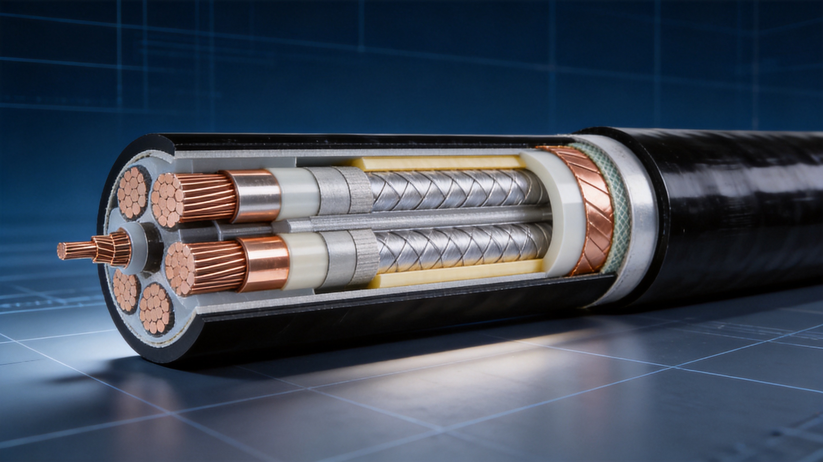
This cable uses a compacted aluminum conductor, cross-linked polyethylene insulation, a three-layer shielding system, thick round steel wire armor, and polyethylene sheathing. Together, these components create a cable structure intended to withstand electrical stress, compression, impact, moisture, corrosion, installation tension, and challenging environmental conditions.
With rated voltage options from 3.6/6kV to 21/35kV and conductor cross-sections from 25mm² to 1200mm², the product can be configured for a wide range of distribution and power transmission projects. Its aluminum conductor makes it a cost-effective alternative to comparable copper-conductor cable, while its steel wire armor improves resistance to external mechanical damage.
The cable is manufactured by Anhui Zhishang Cable Technology Co., Ltd., a Chinese cable producer integrating research and development, production, quality control, and sales. The company operates a modern production base of approximately 5,000 square meters and uses automated production equipment to support standard and customized wire and cable solutions.
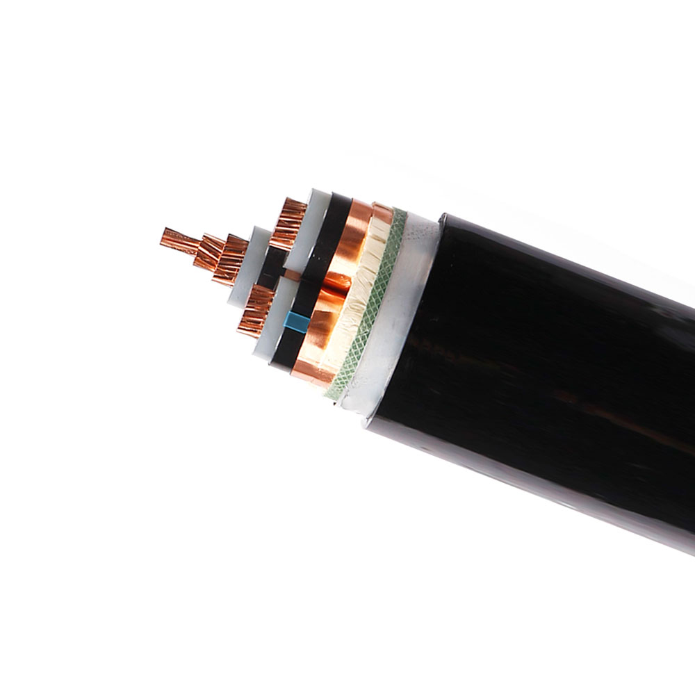
YJLV43 6~35KV Cross-linked Polyethylene Insulated Power Cable
The YJLV43 cable is a medium- and high-voltage power cable based on cross-linked polyethylene insulation. The designation identifies a product family that combines an aluminum conductor with XLPE insulation, steel wire armor, and a polyethylene outer sheath. Its structure is intended to provide stable power transmission while protecting the cable against mechanical and environmental stresses.
Unlike a basic unarmored power cable, this design includes thick round steel wire armor. The armor forms a strong protective layer around the cable core and helps reduce the risk of damage caused by compression, impact, crushing, accidental contact, rodent activity, and difficult installation conditions.
The product also uses a three-layer electrical shielding structure. This structure includes a semi-conductive conductor shield, a semi-conductive insulation shield, and a copper tape shield. The shielding system supports a more uniform electric field around the conductor and insulation, helping to control electrical stress and partial discharge at medium- and high-voltage operating levels.
Polyethylene is used for the inner and outer sheaths. Depending on project requirements, the outer sheath can be specified as standard polyethylene or flame-retardant polyethylene. The black sheath provides a practical finish for outdoor, underground, tunnel, industrial, and infrastructure installations.
The cable is available in multiple voltage classes, including 3.6/6kV, 6/6kV, 6/10kV, 8.7/10kV, 8.7/15kV, 12/20kV, 18/30kV, and 21/35kV. This range allows engineers to select a suitable cable for a specific system voltage, insulation level, and transmission requirement.
The conductor is made from aluminum and can be produced in a compacted round or sector-shaped configuration. Aluminum has a lower material cost and lower density than copper, which can provide meaningful savings in large-scale power transmission projects requiring long cable routes or large conductor cross-sections.
Although aluminum has a higher electrical resistivity than copper, the conductor can be designed with an appropriate cross-sectional area to meet the required current-carrying and voltage-drop requirements. The available range of 25mm² to 1200mm² provides flexibility for different load levels and transmission distances.
The compacted structure reduces gaps between conductor wires and creates a more efficient cable geometry. It can help reduce the overall cable diameter compared with a loosely stranded conductor of equivalent nominal area. A more compact conductor may also support more efficient insulation extrusion and improved dimensional consistency.
Aluminum conductor systems require appropriate installation practices. The surfaces must be properly prepared, and cable accessories must be suitable for aluminum. Medium- and high-voltage terminations and joints should use connection technology and fittings specifically designed for aluminum conductors. Correct torque, contact pressure, oxidation control, and accessory compatibility are essential for long-term performance.
Cross-linked polyethylene is the primary insulation material. XLPE is widely used in power cable systems because it combines high dielectric strength, low dielectric loss, good thermal performance, and strong resistance to moisture and many common chemicals.
The long-term operating temperature of the cable is specified as up to 90°C under appropriate installation and loading conditions. This temperature capability can provide a useful operating margin compared with older thermoplastic insulation systems. During a short circuit, the conductor temperature may reach up to 250°C for a maximum duration of five seconds, subject to the applicable design and installation conditions.
The insulation thickness is determined according to the voltage class and complies with the relevant requirements of GB/T 12706.2. Proper control of insulation thickness, concentricity, cleanliness, and extrusion quality is particularly important for medium- and high-voltage cables because imperfections can increase electrical stress and reduce service reliability.
The cable uses a conductor shield, an insulation shield, and a copper tape shield. These layers serve different but complementary electrical functions.
The semi-conductive conductor shield is applied over the conductor. It helps smooth the external surface of the conductor and reduces localized electric field concentration. This is important because sharp irregularities or voids between the conductor and insulation can create areas of increased electrical stress.
The semi-conductive insulation shield is applied over the XLPE insulation. It helps maintain a controlled electrical boundary and supports a more uniform distribution of voltage stress throughout the insulation system.
The copper tape shield provides an electrically conductive layer around the insulated core. It can assist with the control of induced voltage, provide a path for fault current when correctly connected, and help protect the surrounding cable structure from electrical interference. Shield grounding and bonding should be designed according to the system configuration, cable length, fault level, and applicable electrical codes.
At voltage levels from 6kV to 35kV, consistent shield construction is essential. The three-layer system is therefore one of the most important features of the product. It contributes to stable electrical performance and helps control partial discharge when the cable is correctly manufactured, installed, terminated, and tested.
The armored layer is formed from thick round steel wires. Compared with an unarmored cable, this structure provides a higher level of mechanical protection in environments where cables may experience pressure, impact, pulling forces, ground movement, or accidental contact with construction equipment.
Steel wire armor can be particularly useful for direct burial, industrial cable routes, tunnels, pipelines, bridge infrastructure, and other installations where cable protection cannot rely solely on a separate conduit or concrete channel. It can also help reduce the risk of damage from rodents and other external hazards.
The armor improves the cable’s resistance to tensile forces during installation. The specified tensile performance is at least 12,000N for 6–10kV cables and at least 15,000N for 20–35kV cables. Actual installation tension must remain within the limits approved for the specific cable construction, and suitable pulling equipment, rollers, and bending controls should be used.
Steel armor also affects cable weight, bending behavior, grounding arrangements, and transportation requirements. Engineers should consider the installation route, support spacing, pulling length, cable drum dimensions, and termination design before ordering or installing the cable.
The cable includes a polyethylene inner sheath and an outer sheath made from polyethylene or flame-retardant polyethylene. The sheath provides protection against moisture, corrosion, abrasion, and contact with the surrounding installation environment.
Polyethylene has good water resistance and can support long-term installation in wet locations when the complete cable system is correctly designed. The outer sheath also separates the armor from external contaminants and helps preserve the integrity of the electrical and mechanical layers beneath it.
For projects with additional fire-performance requirements, flame-retardant polyethylene may be considered. The final specification should identify the required fire, smoke, toxicity, chemical-resistance, and environmental classifications because these requirements vary between underground, industrial, tunnel, marine, and building applications.
Product type | Aluminum conductor, XLPE insulated, steel wire armored, polyethylene sheathed power cable |
Voltage range | 3.6/6kV to 21/35kV |
Available conductor cross-section | 25mm² to 1200mm² |
Conductor form | Compacted round or sector-shaped aluminum conductor |
Insulation | Cross-linked polyethylene |
Electrical shielding | Semi-conductive conductor shield, semi-conductive insulation shield, and copper tape shield |
Armor | Thick round steel wire armor |
Inner sheath | Polyethylene |
Outer sheath | Polyethylene or flame-retardant polyethylene |
Long-term conductor operating temperature | Up to 90°C |
Short-circuit temperature | Up to 250°C for five seconds |
Insulation resistance | At least 1000MΩ·km at 20°C |
Partial discharge | Not more than 10pC at 1.73U₀ |
Minimum bending radius | 25 times the outer diameter for multi-core cable; 20 times the outer diameter for single-core cable |
Minimum installation temperature | −10°C |
Sheath color | Black |
Reference standards | GB/T 12706.2 and GB/T 3956, according to the applicable product configuration |
The listed specifications provide a general product framework. The final cable design should be confirmed against the project’s voltage system, current rating, installation method, short-circuit level, environmental conditions, fire requirements, and accessory requirements.
One of the most significant advantages of the product is its aluminum conductor. Aluminum is generally less expensive than copper and is more readily available for large-scale conductor production. For long transmission routes or high-capacity projects requiring substantial conductor volume, the material-cost difference can have a major influence on the total project budget.
The lower density of aluminum can also reduce conductor weight. This may simplify some transportation and handling operations, although the total cable weight must include the steel armor, insulation, shielding, and sheathing. The project team should therefore compare the complete cable weight rather than the conductor weight alone.
Aluminum cable is especially attractive when the design allows a moderately larger conductor cross-section to achieve the required electrical performance. By balancing conductor area, voltage drop, ampacity, installation space, and accessory cost, engineers can achieve a cost-effective cable system without sacrificing the required voltage rating.
Unarmored cable may require additional ducts, protective pipes, concrete covers, or specialized supports when installed in areas exposed to mechanical hazards. The thick steel wire armor of the YJLV43 construction provides integrated protection and may reduce the need for some supplementary protection measures.
The armored construction is suitable for routes where cables may be buried directly or placed in difficult environments. It is intended to resist crushing, impact, pulling forces, and external interference more effectively than a comparable unarmored design.
This protection is valuable in industrial plants, mines, tunnels, bridges, ports, utility corridors, and infrastructure projects where the cable route may be exposed to maintenance activity, construction equipment, vibration, or ground pressure.
The combination of XLPE insulation and three-layer shielding supports reliable performance at medium- and high-voltage levels. XLPE offers low dielectric loss and good insulation resistance, while the shielding system helps control electrical stress at the conductor and insulation interfaces.
The specified partial-discharge performance of not more than 10pC at 1.73U₀ reflects the importance of electrical quality control. Low partial discharge is desirable because repeated localized discharge can gradually weaken insulation and reduce service life.
Electrical performance depends on more than the insulation material alone. Clean production conditions, precise extrusion, stable material formulation, controlled curing, accurate shielding application, and effective testing are all required to achieve consistent results.
Polyethylene sheathing provides a practical barrier against moisture and many common corrosive influences. The cable is therefore suitable for a range of outdoor, underground, tunnel, pipeline, and industrial applications where the surrounding environment may be damp or chemically aggressive.
The cable’s water resistance is described as excellent and suitable for long-term underwater installation. However, underwater and deep-sea projects require a complete engineering assessment. Water pressure, installation depth, dynamic movement, seabed conditions, marine growth, anchor hazards, cyclic bending, jointing, and corrosion protection must all be considered.
For permanent underwater routes, the cable should be selected and tested as part of a complete system. Additional requirements may include water-blocking measures, special joints, corrosion-resistant components, mechanical restraints, and installation procedures developed for the specific water depth and route profile.
The armor increases tensile strength and provides a more robust cable body during handling. This can be beneficial during long-distance pulling operations and installation in routes with complex geometry. The cable’s defined minimum bending radius provides an important reference for drum handling, turning points, cable support, and final positioning.
Correct installation remains essential. The cable should not be forced below its minimum bending radius, dragged over sharp surfaces, exposed to uncontrolled impact, or pulled beyond its approved tension. Proper rollers and guides help protect the outer sheath and armor during installation.
Once installed, the robust sheath and armor may reduce the likelihood of external damage, supporting lower maintenance requirements. If a fault does occur, the cable’s construction and test records can assist technicians in identifying the affected section and selecting suitable repair or jointing procedures.
The cable is suitable for direct-buried power routes when the trench, backfill, thermal conditions, drainage, and mechanical protection have been properly designed. The armor helps protect the cable from soil pressure, stones, accidental excavation, and rodent activity.
Direct burial can reduce the need for continuous conduit systems and may simplify long-distance utility construction. However, the installation design should account for heat dissipation, grouping, soil thermal resistivity, burial depth, cable spacing, grounding, and future access requirements.
Tunnels and utility corridors often contain numerous power, control, communication, water, and gas systems. Cables in these environments must be routed safely and protected from vibration, moisture, maintenance traffic, and restricted ventilation conditions.
The armored structure provides mechanical protection, while the optional flame-retardant polyethylene sheath may be considered where the project has additional fire-performance requirements. Engineers should review the complete fire-safety specification rather than relying on a single material description.
Industrial plants, processing facilities, substations, water treatment systems, warehouses, transport infrastructure, and large machinery installations require power cables that can withstand demanding operating conditions. The YJLV43 construction can be used for feeders, distribution links, plant power supplies, and connections between electrical equipment when the voltage and current requirements are suitable.
The aluminum conductor can reduce project cost, while the steel wire armor helps protect cables routed through industrial areas. XLPE insulation supports continuous operation at elevated conductor temperatures, provided that the installation design maintains appropriate heat dissipation.
The cable is described for underwater outgoing lines from large hydropower stations and other water-related power transmission systems. Such projects may involve wet shafts, river crossings, submerged sections, intake structures, and difficult access conditions.
The cable’s water-resistant polyethylene sheath and mechanical armor are valuable characteristics for these installations. Nevertheless, project designers should verify whether the cable is intended for static or dynamic service, whether additional water-blocking construction is required, and whether the cable has been qualified for the specific hydraulic and mechanical conditions.
Cross-river and cross-sea power connections can present a combination of water exposure, installation tension, route movement, abrasion, and external impact. The product’s strong armor and polyethylene sheath make it a candidate for heavy underwater engineering applications where cost control is also important.
For cross-sea routes, engineers must consider tidal currents, seabed movement, anchor impact, fishing activity, installation vessels, burial depth, cable protection at landfalls, and long-term joint reliability. A cable suitable for a static submerged route may not automatically be suitable for a highly dynamic application.
Medium- and high-voltage power transmission is essential for offshore oil and gas platforms. Cables may be installed between generation equipment, substations, processing units, accommodation modules, and subsea facilities.
The cable’s water resistance and armor can provide useful protection for selected offshore routes. The final specification must also address oil resistance, flame performance, low-smoke requirements, toxicity, electromagnetic compatibility, platform classification, and applicable marine standards where relevant.
Reliable cable production begins with controlled raw materials. Aluminum conductor material, XLPE insulation compounds, semi-conductive materials, copper tape, steel armor wires, and polyethylene sheath compounds must meet the required technical specifications before entering production.
Incoming inspection may include dimensional checks, surface inspection, electrical resistance verification, material identification, and documentation review. Aluminum conductor material should be checked for suitable conductivity, mechanical consistency, cleanliness, and compatibility with the intended stranding process.
Insulation and sheath compounds require careful storage and handling. Moisture, contamination, incorrect batch identification, or unsuitable storage conditions can affect extrusion quality. Material traceability allows production teams to associate finished cable with specific raw material batches and process records.
The aluminum wires are stranded to form a round or sector-shaped conductor. During this process, the production line controls wire tension, lay length, conductor dimensions, and surface quality. Compaction reduces voids and improves the conductor’s geometric uniformity.
Accurate conductor dimensions are important because they influence insulation thickness, cable diameter, electrical resistance, bending behavior, and the fit of cable accessories. Production personnel must control the conductor profile throughout the process rather than relying only on a final inspection.
The conductor is also checked for continuity and resistance. Compliance with the corresponding requirements of GB/T 3956 helps ensure that the conductor’s direct-current resistance is appropriate for its nominal cross-section and material class.
The conductor shield, insulation, and insulation shield are applied through controlled extrusion. For medium- and high-voltage cable, this process is commonly performed with close attention to concentricity, cleanliness, temperature, pressure, line speed, and material flow.
A stable extrusion process helps reduce the risk of voids, surface defects, eccentric insulation, contamination, and irregular interfaces. The conductor shield must be applied uniformly over the conductor, while the XLPE layer must maintain the specified thickness for the voltage class.
After extrusion, the insulation is cross-linked under controlled thermal conditions. Cross-linking changes the molecular structure of the polyethylene and gives the insulation its desired thermal and mechanical properties. Temperature, pressure, residence time, and cooling conditions must be maintained consistently to achieve reliable insulation performance.
The insulation shield is applied over the XLPE layer to form a controlled electrical boundary. The finished insulated core is inspected for diameter, surface smoothness, concentricity, and visible defects before moving to the next stage.
The copper tape shield is applied around the insulated core with controlled overlap and tension. A consistent shield is important for electrical continuity, mechanical stability, and reliable termination preparation.
Shielding quality is checked through visual inspection, dimensional verification, and electrical continuity testing. Production staff also verify that the tape remains correctly positioned and is not damaged during subsequent cabling and armor application.
The polyethylene inner sheath separates the shielded core from the armored layer. It supports structural integrity and provides a protective surface for armor application.
During extrusion, the line controls sheath thickness, diameter, surface quality, color, and adhesion characteristics. The inner sheath must be free from pinholes, cracks, excessive roughness, and other defects that could reduce mechanical or environmental protection.
Thick round steel wires are applied around the inner-sheathed core. The armor machine controls wire tension, lay direction, pitch, and coverage. Consistent armor application helps distribute external mechanical forces and supports the specified tensile performance.
Steel wire condition is important. The wires should have suitable dimensional accuracy, surface condition, strength, and corrosion protection. Armor continuity and uniformity are checked during production, and the finished cable is inspected for loose wires, excessive gaps, protrusions, or irregular formation.
The final polyethylene or flame-retardant polyethylene sheath is extruded over the armored structure. This layer provides the primary external barrier against moisture, abrasion, corrosion, and installation-related surface damage.
The black outer sheath is inspected for thickness, diameter, smoothness, marking, and surface integrity. Cable identification markings may include product type, voltage level, conductor size, manufacturer information, and production traceability details according to the order specification.
Finished cable undergoes electrical, dimensional, mechanical, and appearance inspections. The testing program is selected according to the applicable standards and the customer’s technical requirements.
Power-frequency withstand voltage testing verifies that the cable can withstand the specified test voltage. The stated test condition is 2.5U₀ plus 2kV for five minutes. Insulation resistance testing verifies the cable’s resistance at 20°C, with a specified value of at least 1000MΩ·km.
Partial-discharge testing is particularly significant for medium- and high-voltage cable. The specified limit is not more than 10pC at 1.73U₀. Partial-discharge testing can identify defects or irregularities that may not be visible through ordinary inspection.
Additional inspections may include conductor resistance, dimensional measurement, sheath integrity, armor continuity, impulse withstand performance, and mechanical tests. Test reports provide evidence that the finished cable has been evaluated against the required product criteria.
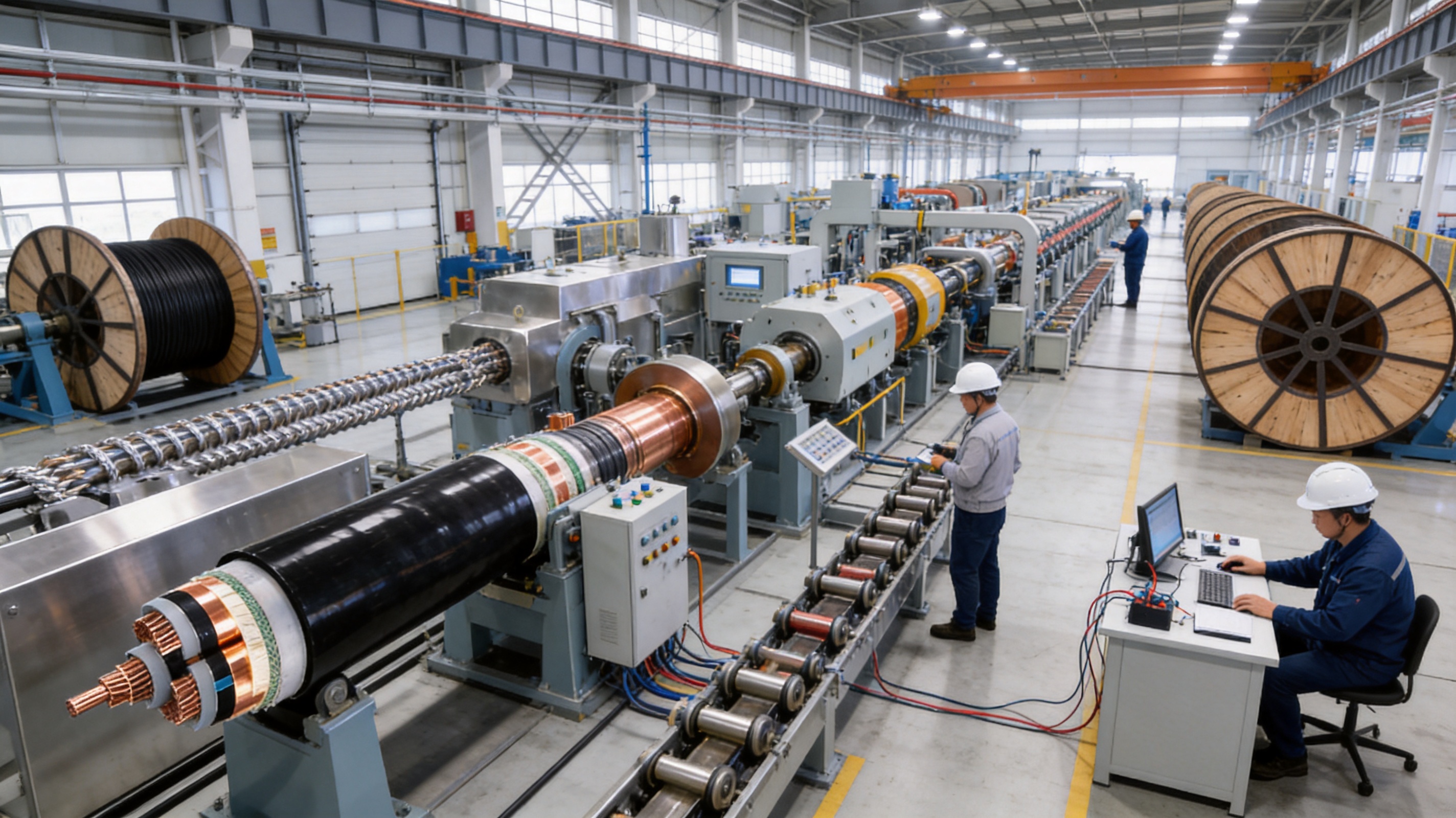
Anhui Zhishang Cable Technology Co., Ltd. integrates product research and development, manufacturing, quality management, and sales. This integrated structure allows technical information to move more directly between engineering, production, inspection, and customer service teams.
The company operates a production base of approximately 5,000 square meters with more than ten automated production lines. The reported monthly output can reach up to ten million meters, supporting both regular product programs and larger project requirements.
A team of more than fifty employees includes quality engineers and research-and-development technicians with more than ten years of industry experience. This experience is valuable for products that require precise conductor design, controlled insulation extrusion, specialized armor construction, and project-specific technical documentation.
The company supports OEM and ODM development based on customer drawings, samples, or defined technical requirements. For cable buyers, this means that the product can potentially be adjusted for conductor size, voltage class, sheath material, shielding structure, armor arrangement, color, marking, packaging, and other project requirements.
Technical engineers provide product-selection guidance and customized cable design support. This is important because cable selection should be based on the complete operating environment rather than voltage rating alone. Current, installation method, ambient temperature, grouping, short-circuit level, bending route, water exposure, fire performance, and termination technology all affect the final design.
The company also provides standard cable models with full-core and full-length specifications, pure copper options where required, product test reports, and warranty support. Standard products may be stocked for faster shipment, while customized products generally require a lead time of approximately seven to twenty days, depending on construction complexity, material availability, quantity, and testing requirements.
Production automation can improve consistency by stabilizing line speed, material feeding, extrusion temperature, conductor tension, and dimensional control. Automation does not replace engineering judgment or inspection, but it can reduce variation and support repeatable production when combined with qualified personnel and documented procedures.
Before installation, the route should be surveyed for length, elevation changes, bends, access points, soil conditions, water exposure, possible interference, and future maintenance requirements. The cable drum length should be matched to the route to minimize unnecessary joints.
For direct burial, the trench should be free from sharp rocks and construction debris. Appropriate bedding and backfill materials should be used. Where the cable crosses roads, foundations, drainage channels, or other utility systems, additional mechanical protection may be required.
Cable drums should be transported and positioned according to their markings. The drum should rotate in the indicated direction during unwinding. Sudden braking, uncontrolled rolling, and dragging can damage the sheath or distort the armor.
During pulling, the installation team should monitor tension and bending radius. The minimum bending radius is specified as 25 times the cable outer diameter for multi-core cable and 20 times the cable outer diameter for single-core cable. If the exact project configuration differs, the approved technical datasheet should govern.
Rollers should be placed at suitable intervals, especially near bends and vertical transitions. Pulling socks, swivels, and other accessories must be compatible with the cable construction. The armor should not be used as an improvised pulling point unless the installation method has been specifically approved.
Aluminum conductors require suitable connectors, lugs, joints, and termination systems. The conductor surface should be prepared according to the accessory manufacturer’s instructions, and oxidation control should be addressed where required.
Incorrect accessory selection can create excessive contact resistance, localized heating, or mechanical weakness. Medium- and high-voltage joints must also preserve the conductor shield, XLPE insulation interface, insulation shield, and metallic shielding continuity.
Installation personnel should follow the approved jointing procedure and use calibrated tools. After installation, the completed cable system should undergo the required electrical tests before energization.
The copper tape shield and armor must be connected according to the electrical system design. Grounding arrangements can affect induced voltage, circulating current, fault-current capacity, electromagnetic compatibility, and personnel safety.
Single-point bonding, both-end bonding, and cross-bonding arrangements may be appropriate in different applications. The correct method depends on cable length, configuration, system voltage, fault level, and local regulations. Grounding should therefore be designed by qualified electrical engineers.
The product information identifies deep-sea submarine transmission, underwater hydropower outgoing lines, cross-sea and cross-river bridge supplies, offshore oil and gas platforms, and extreme underwater environments as application areas. These applications require careful project-specific validation.
A static underwater cable and a dynamic submarine cable do not experience the same stresses. A static route may remain fixed on or below the seabed, while a dynamic cable can experience repeated bending, vibration, tension variation, and movement caused by waves or currents. The cable construction, armor, sheath, joints, and support system must be suitable for the intended service.
Water depth affects external pressure and installation tension. Seabed conditions influence abrasion, burial stability, thermal dissipation, and long-term movement. Currents can cause free spans, vortex-induced vibration, or movement around support points. Near shore, wave action and tidal movement can create additional mechanical stress.
Anchor impacts, fishing activity, dredging, vessel traffic, and marine construction are potential external hazards. The thick steel wire armor offers an important level of mechanical protection, but route protection, burial, rock placement, protective conduits, or other measures may still be necessary.
Underwater cable joints and landfall transitions deserve special attention. They must provide electrical insulation, water resistance, mechanical strength, and long-term sealing. The project may also require special bend restrictors, termination structures, corrosion-resistant components, and monitoring systems.
For these reasons, the YJLV43 cable should be selected for underwater projects only after reviewing the complete technical specification, qualification evidence, installation method, and environmental design. The product’s water-resistant construction is a strong starting point, but suitability must be confirmed for the actual depth, movement, loading, and service life requirements.
The cable’s insulation thickness and sheath thickness are specified according to GB/T 12706.2, while conductor resistance is related to the applicable requirements of GB/T 3956. These standards provide a technical basis for cable dimensions, materials, electrical characteristics, and testing.
Project purchasers should request the documentation required for their application. Typical documents may include technical datasheets, material certificates, routine test reports, type-test information where applicable, inspection records, packing lists, installation recommendations, and warranty terms.
For export projects, buyers may also require additional standards or certifications, such as CE or RoHS-related documentation, depending on the destination market and application. The applicable requirements should be confirmed before production because certification, marking, testing, and documentation can affect the product configuration and delivery schedule.
Traceability is another important aspect of quality assurance. Cable markings, drum numbers, production dates, conductor batch records, insulation material records, and test results help connect the finished product with its manufacturing history. This information can simplify inspection, installation, maintenance, and future technical support.
The value of a power cable should be assessed over the complete project lifecycle rather than by purchase price alone. The YJLV43 design offers several factors that may reduce total project cost.
First, the aluminum conductor can lower material expenditure compared with a similar copper-conductor product. Second, the integrated armor may reduce the need for additional external protection in some installation conditions. Third, XLPE insulation and polyethylene sheathing support long-term reliability when properly installed. Fourth, the company’s manufacturing capacity and standard product availability may help shorten procurement schedules.
At the same time, the buyer should evaluate all associated costs. Aluminum may require specialized accessories and installation procedures. Armored cable is heavier and may require stronger support systems. Large cross-sections may need larger drums, specialized pulling equipment, and experienced jointing teams.
A balanced comparison should therefore include conductor material, cable cross-section, armor construction, accessories, transportation, installation equipment, testing, maintenance, and expected service life. When these factors are considered together, the product can provide a practical balance between investment cost and mechanical and electrical performance.
Project engineers can use the following sequence when evaluating the cable:
1. Confirm the system voltage and required rated voltage class.
2. Calculate continuous current, emergency loading, voltage drop, and short-circuit requirements.
3. Select the conductor material and cross-section based on electrical performance and project economics.
4. Confirm whether a compacted round or sector-shaped conductor is more suitable for the installation.
5. Define the shielding and grounding arrangement.
6. Determine whether steel wire armor is required for direct burial, underwater service, tunnel installation, or industrial protection.
7. Specify standard or flame-retardant polyethylene sheathing according to the environmental and fire requirements.
8. Check the minimum bending radius, maximum pulling tension, cable drum dimensions, and route geometry.
9. Confirm suitable aluminum-compatible terminations, joints, lugs, and grounding accessories.
10. Review testing, certification, inspection, packaging, delivery, and warranty requirements.
11. For underwater or offshore projects, complete a route-specific mechanical and environmental assessment.
This process helps ensure that the selected cable is matched to the actual application rather than chosen solely by voltage rating or conductor area.
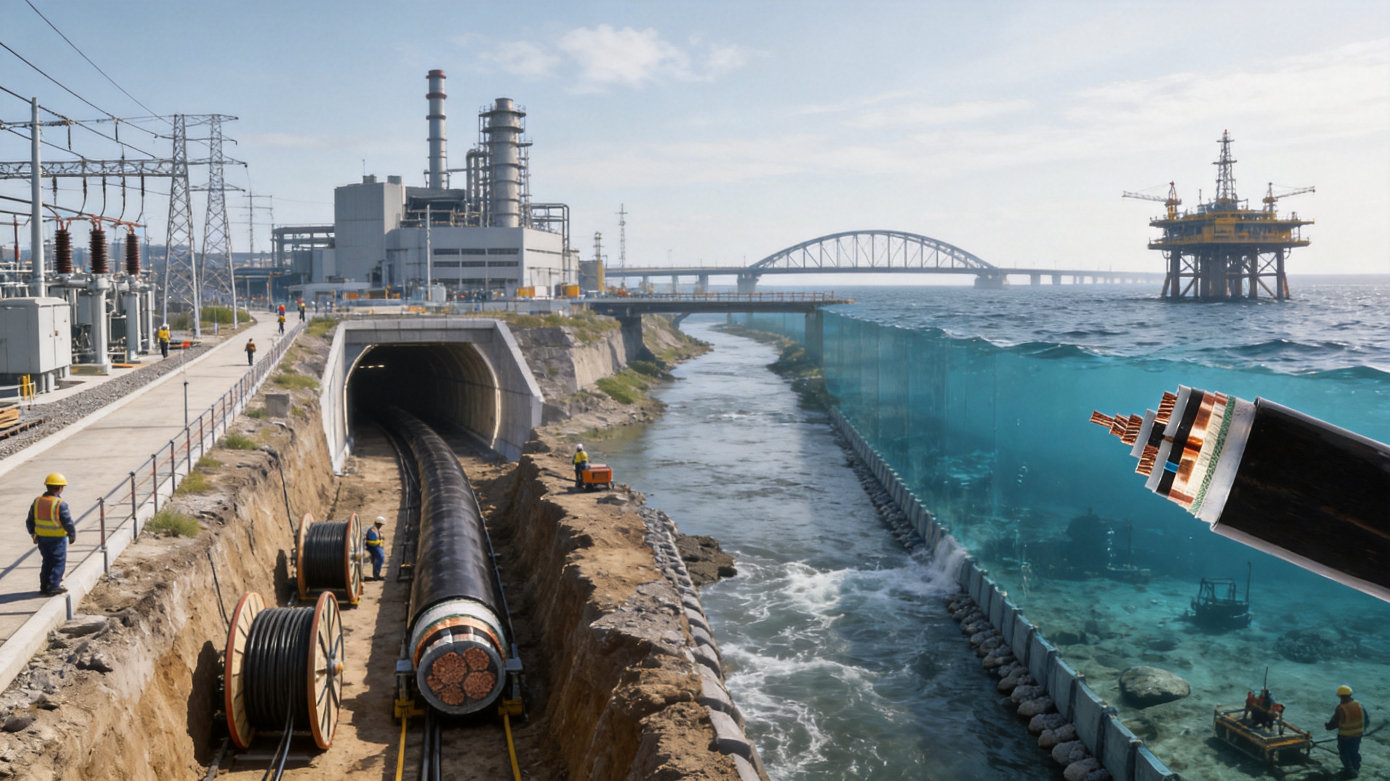
The main advantage is the combination of cost-effective aluminum conductivity, XLPE insulation, three-layer electrical shielding, thick steel wire armor, and polyethylene sheathing. This combination provides a balance of electrical performance, mechanical protection, water resistance, and project economy.
The listed voltage options include 3.6/6kV, 6/6kV, 6/10kV, 8.7/10kV, 8.7/15kV, 12/20kV, 18/30kV, and 21/35kV. The correct selection depends on the system’s nominal voltage, insulation coordination, and applicable standards.
Aluminum generally costs less and has a lower density than copper. It can provide an economical solution for long-distance and high-capacity transmission when the conductor cross-section is selected appropriately. Aluminum-compatible connection technology must be used for medium- and high-voltage terminations and joints.
The conductor shield smooths the conductor surface and helps reduce electric field concentration. The insulation shield controls the electrical boundary around the XLPE insulation. The copper tape shield supports electrical shielding, fault-current paths, and grounding functions when correctly connected.
Yes, the armored construction is suitable for many direct-buried applications. The trench, bedding, backfill, thermal conditions, burial depth, and route protection must be designed correctly. The installation must also comply with the approved cable tension and bending requirements.
The cable is designed with polyethylene sheathing and thick steel wire armor for strong water resistance and mechanical protection, and it is identified for underwater engineering applications. However, underwater suitability must be confirmed for the specific depth, pressure, movement, seabed condition, installation method, and required service life.
The specified long-term operating temperature is up to 90°C. The actual allowable current depends on installation conditions, ambient temperature, cable grouping, soil thermal resistivity, ventilation, and other heat-dissipation factors.
The specified short-circuit temperature is up to 250°C for five seconds. The short-circuit rating must be checked against the conductor area, fault duration, system protection settings, and applicable design calculations.
The listed minimum bending radius is 25 times the cable outer diameter for multi-core cable and 20 times the cable outer diameter for single-core cable. The approved technical data for the final construction should be followed during transportation and installation.
Aluminum connections require suitable lugs, joints, and termination systems. Surface preparation, oxidation control, contact pressure, torque, and accessory compatibility must be managed according to the approved installation procedure.
The manufacturer integrates research and development, production, sales, and quality control. Its approximately 5,000-square-meter facility includes more than ten automated production lines and supports standard products as well as OEM and ODM cable development.
Customization support is available based on customer drawings, samples, and defined project requirements. Possible variables may include conductor size, voltage class, sheath material, armor structure, markings, color, packaging, and other technical parameters, subject to engineering review.
The listed requirements include conductor resistance according to the applicable conductor standard, insulation resistance of at least 1000MΩ·km at 20°C, partial discharge of not more than 10pC at 1.73U₀, power-frequency withstand testing, impulse withstand performance, dimensional inspection, sheath checks, and other applicable routine or type tests.
The outer sheath can be specified as polyethylene or flame-retardant polyethylene. The required fire-performance level should be defined before production because different tunnels, industrial facilities, offshore projects, and building installations may have different fire and smoke requirements.
A complete inquiry should include rated voltage, conductor material, conductor cross-section, number of cores, installation method, cable length, environmental conditions, armor requirements, sheath requirements, fire-performance needs, test requirements, delivery destination, and any applicable certification or project standards.
The YJLV43 6–35kV cross-linked polyethylene insulated power cable is designed for medium- and high-voltage transmission where electrical stability, mechanical protection, water resistance, and cost control are all important. Its aluminum conductor helps reduce material cost, while XLPE insulation supports reliable thermal and dielectric performance.
The three-layer shielding system is designed to control electrical stress and partial discharge. Thick round steel wire armor provides strong resistance to compression, impact, tensile loading, and external damage. Polyethylene inner and outer sheaths provide protection against moisture and corrosion, with a flame-retardant sheath option available for selected applications.
The product is suitable for consideration in direct-buried networks, industrial facilities, tunnels, pipelines, bridge infrastructure, hydropower projects, offshore installations, and selected underwater transmission systems. Underwater and deep-sea use must be evaluated through a complete route-specific engineering review.
The manufacturer strengthens the product offering through automated production lines, experienced engineering personnel, integrated quality control, OEM and ODM support, test documentation, standard product availability, and customized cable design services. These capabilities allow the cable to be adapted to different voltage levels, conductor sizes, environmental conditions, and project specifications.
When correctly selected, manufactured, installed, terminated, and tested, this armored XLPE power cable can provide a practical and reliable solution for demanding power transmission projects that require a balance between performance and overall cost.
GB/T 12706.2, Power Cables with Extruded Insulation and Their Accessories for Rated Voltages from 1kV to 35kV.
GB/T 3956, Conductors of Insulated Cables.
IEC 60502-2, Power Cables with Extruded Insulation and Their Accessories for Rated Voltages from 6kV to 30kV.
IEC 60840, Power Cables with Extruded Insulation and Their Accessories for Rated Voltages Above 30kV up to 150kV.
IEC 60228, Conductors of Insulated Cables.
Technical product information for YJLV43 6–35kV cross-linked polyethylene insulated power cable.
Manufacturer-provided information on cable production, quality control, customization, testing, and application guidance.

We firmly believe that good cables are not only a competition of materials, but also a reflection of craftsmanship, quality, and responsibility.

Links
Product
Send Inquiry
No. 29 Sankeshu Road, Xuanzhou District, Xuancheng City, Anhui Province, China
+86-18621104555/+86-563-2622999
 Electrical Cable Manufacturer
OEM/ODM Wire and Cable Solutions
Electrical Cable Manufacturer
OEM/ODM Wire and Cable Solutions
 English
 Español
 عربى
عربى
 русский